Switch rail of turnout junction for railway and connection device for rotary handle

A technology of rotating handle and connecting device, applied in the direction of roads, tracks, switches, etc., can solve the problem of separation of the tip rail and the rotating handle, and achieve the effect of increasing the difficulty of being pulled off, preventing the train from derailing, and quickly assembling and forming.

Active Publication Date: 2017-07-04
曹大明 +3
View PDF6 Cites 0 Cited by
  • Summary
  • Abstract
  • Description
  • Claims
  • Application Information

AI Technical Summary

Problems solved by technology

[0004] The purpose of the present invention is to solve the problem that the switching force transmitted from the rotating handle to the switch rail and the vibration of the switch rail caused by the passing of the vehicle lead to the separation of the switch rail and the rotating handle

Method used


Image

  • Switch rail of turnout junction for railway and connection device for rotary handle
  • Switch rail of turnout junction for railway and connection device for rotary handle
  • Switch rail of turnout junction for railway and connection device for rotary handle

Examples


Embodiment Construction

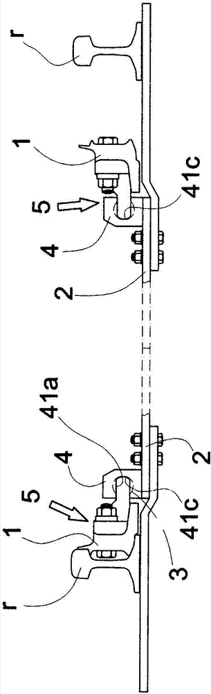
[0023] Past examples such as Figure 4 As shown, the rotating handle 2 is not an integral rod along the length direction, but consists of a pair of rod parts 2a, 2b, which can be arranged in the middle part to generate mutually insulated signal parts between the switch rails, and use bolts and A combined rod connected by nuts, etc. Since the present invention has nothing to do with the aforementioned components, descriptions and illustrations related thereto are omitted.

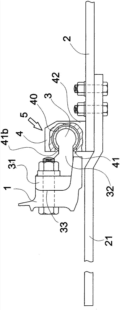
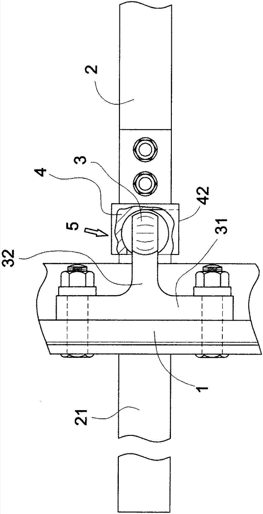
[0024] The term "spherical band" described in the present invention. The term can refer to both figure 1 , 2 , 4, 5, the entire ball zone of the convex part 3 extending from the connecting block 32 to its outer edge can also represent as Figure 7 , 8 , 9, and 10, the outer edge of the convex part 3 is cut vertically to form most of the ball bands, or part of the ball bands in the strict sense, and the corresponding part is the hemispherical hole 4a.

[0025] The present invention, such as figure 1 ...


PUM


Abstract

The present invention provides a switch rail of a turnout junction for a railway and connection device for a rotary handle. The switch force generated when the switch rail is switched from the rotary handle and the switch rail is configured to cause vibration of the switch rail when the vehicle passes through, the bolts and nuts are fixed on the U-shaped metal buckle and the connection plate to cause the loosening and dropping of each nut to separate the switch rail from the rotary handle to finally cause the possibility of the train derailing. the connection device having the switch rail 1 and the rotary handle 2 and the switch rail 1 is employed, and a concave part 4 is formed by outside embedding locking portion 40 corresponding to the bump part 3 formed at the installation portion 5 of the switch rail 1 and the rotary handle 2 to connect together through a concave-convex tabling structure.

Description

technical field [0001] The invention relates to a connecting device of a switch rail and a turning handle of a railway turnout. Background technique [0002] The previous turnout structure, such as Figure 12 As shown, each end of the connecting plates a1, a2 is connected and fixed with each switch rail R1, R2 by bolts and nuts, and the other end of the connecting plates a1, a2 is embedded and fixed in the rotating handle c, and the side is a U-shaped metal fastener e1, e2, and are fixed by bolt b1 and nut b2, so that the switch rails R1, R2 and the rotating handle c are integrated. In this way, as shown by the arrow, the clutch of the switch rails R1, R2 and the basic rails r1, r2 can be switched by moving the turning handle c left and right. [0003] The switching force transmitted from the turning handle to the turning handle generated during the switching of the turning handle (the left and right movement of the turning handle causes the pressing of the turning handle t...

Claims


Application Information

Patent Timeline
Patent Type & Authority Applications(China)
IPC IPC(8): E01B7/02
CPCE01B7/02
Inventor 曹大明陈桦罗休佐藤泰生
Owner 曹大明
Why Eureka
Try Eureka