
Real-time monitoring system for bridge construction

A technology for real-time monitoring and bridge construction, applied in transmission systems, special data processing applications, instruments, etc., can solve problems such as inability to query data, fail to realize real-time monitoring and early warning, and unintuitive display of results, etc., to achieve an intuitive and convenient display of information Effect

Inactive Publication Date: 2017-07-04
CCCC SECOND HARBOR ENG
View PDF5 Cites 15 Cited by
  • Summary
  • Abstract
  • Description
  • Claims
  • Application Information

AI Technical Summary

Problems solved by technology

The current data collection method is generally that the staff collect manually at the construction site at a certain construction progress, and then process the collected raw data into results, but there are many problems such as manual data collection and data processing are prone to errors; only collection time The data at that time, the data in other time periods cannot be queried, and the continuous change of the data cannot be grasped; real-time monitoring and early warning cannot be realized; the results display is not intuitive, etc.
[0003] In recent years, some improved bridge construction monitoring systems have appeared, which improved the manual collection method to automatic collection method, but there are still the following problems: still rely on manual methods in data processing and results display; data display is just a simple list display , it is impossible to have an intuitive understanding of the state of the full bridge

Method used


Image

  • Real-time monitoring system for bridge construction
  • Real-time monitoring system for bridge construction

Examples


Embodiment Construction

[0036] The present invention will be further described in detail below in conjunction with the accompanying drawings, so that those skilled in the art can implement it with reference to the description.

[0037] It should be noted that, in the description of the present invention, the terms "upper", "lower", "front", "rear", "left", "right", "top", "bottom", "inside", " The orientation or positional relationship indicated by "outside", etc. is based on the orientation or positional relationship shown in the drawings, which is only for the convenience of describing the present invention and simplifying the description, and does not indicate or imply that the referred device or element must have a specific orientation, Specific orientation configurations and operations, therefore, are not to be construed as limitations on the invention.

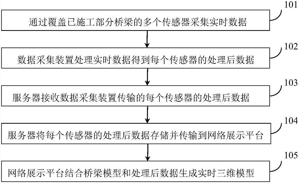
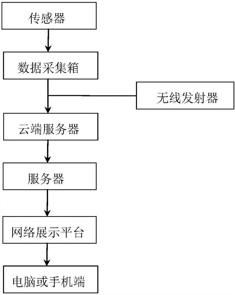
[0038] Such as figure 1 As shown, the present invention provides a bridge construction real-time monitoring system, comprising:

[0039] The...


PUM


Abstract

The present invention discloses a real-time monitoring system for bridge construction. The system comprises: a data collection device, wherein, after collecting real-time data by covering a plurality of sensors of a constructed part of a bridge, the data collection device is used for processing real-time data and obtaining processed data corresponding to each sensor; a server, wherein the server is used for receiving and storing the processed data of each sensor transmitted by the data collection device; and a network display platform, wherein sensor models are arranged at a corresponding position in a bridge model established on the network display platform to an actual bridge, and the network display platform is used for receiving processed data of each sensor transmitted by the server, corresponding the processed data to the sensor model respectively, and generating a real-time three-dimensional model based on the bridge model. According to the system disclosed by the present invention, data is automatically collected all the time by using the data collection device, and result data is visualized in the real-time three-dimensional model by setting the sensor model corresponding to the actual bridge on the network display platform, so that bridge construction information is displayed more intuitively.

Description

technical field [0001] The invention relates to the field of bridge construction monitoring. More specifically, the present invention relates to a bridge construction real-time monitoring system. Background technique [0002] Bridge construction monitoring is to read the installed sensors on the bridge during the bridge construction process, and compare the measured data with the theoretical value to ensure the smooth progress of the bridge construction. The current data collection method is generally that the staff collect manually at the construction site at a certain construction progress, and then process the collected raw data into results, but there are many problems such as manual data collection and data processing are prone to errors; only collection time The data at that time, the data of other time periods cannot be queried, and the continuous change of the data cannot be grasped; real-time monitoring and early warning cannot be realized; the results display is n...

Claims


Application Information

Patent Timeline
IPC IPC(8): G06F17/30G06Q50/08H04L29/08
CPCG06Q50/08G06F16/248G06F16/252H04L67/12
Inventor 李浩田唯朱浩项梁黎晖白佳翁方文
Owner CCCC SECOND HARBOR ENG
Learn More