
Remote-network signature apparatus

A remote network and seal technology, applied in printing, stamping and other directions, can solve problems such as inability to stamp authority and usage management and control, time delay, and low efficiency.

Inactive Publication Date: 2007-04-18
张立安
View PDF0 Cites 34 Cited by
  • Summary
  • Abstract
  • Description
  • Claims
  • Application Information

AI Technical Summary

Problems solved by technology

However, the current invalid management of seals gives many lawbreakers opportunities to take advantage of, which leads to economic crimes. Many major economic cases have an important relationship with the illegal use of seals, and some are even the main reason
At present, the process of affixing a seal mostly adopts the traditional manual method of stamping with force. This traditional method of affixing the seal is likely to cause the seal to be unclear due to uneven force and uneven distribution of the ink pad, which makes the identification of the seal troublesome and often needs to be reprinted. Affix a seal or invalidate the stamped document; in addition, manual affixing makes the control and management of the seal troublesome, and the seal management personnel need to carry the seal with them or lock the seal in the area under their control, so that once the seal management personnel are not in the seal Next to it, when it is necessary to affix a seal on the document as soon as possible, it will cause time delays, affect work efficiency, and even cause economic losses; and if the seal management personnel hand over the seal to other personnel in advance, it is difficult to carry out the seal inspection. Effective control, once certain documents are stamped without authorization, it will cause great economic losses to the seal owner
[0003] At present, there is also a stamping machine with uniform force and clear seal image on the market. The Chinese patent announcement number is CN 2351283Y, and the announcement date is December 1, 1999. A kind of such stamping machine is disclosed. Its disadvantages are: the stamping process is still manual operation, and it cannot effectively manage and control the authority and use of the stamp stamping, and its safety performance is poor; its stamps can only be vertically vertical Movement, the position on the horizontal plane cannot be moved back and forth, left and right, so it can only be stamped on documents with a fixed size and a fixed position of the stamp. It cannot stamp a variety of documents and documents with different stamping positions, and its application range is small. , for enterprises and departments with many seals and stamped documents, multiple stamping machines are required
[0004] Therefore, the existing technology has the following deficiencies: the automatic stamping cannot be controlled by remote signals, the safety performance is poor, and the efficiency is low

Method used


Image

  • Remote-network signature apparatus
  • Remote-network signature apparatus
  • Remote-network signature apparatus

Examples


Embodiment 1

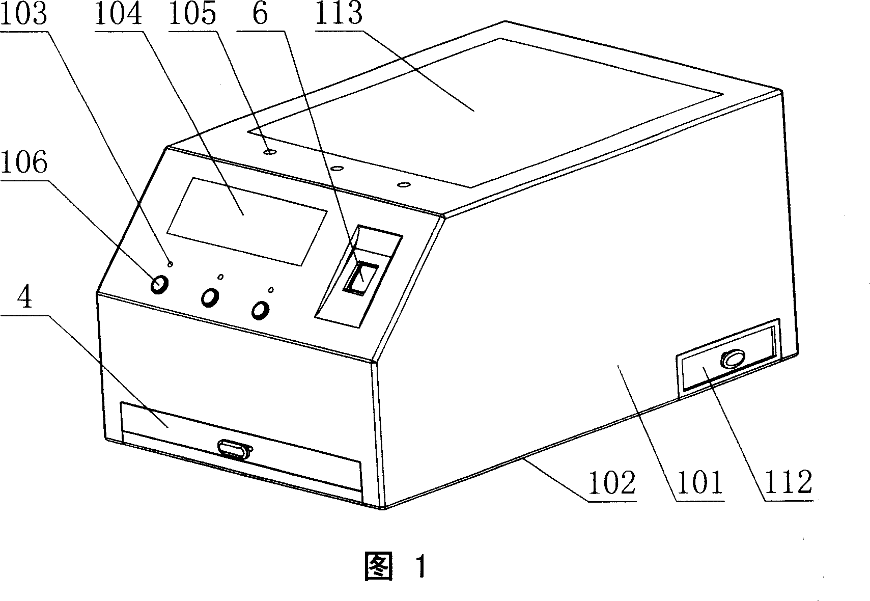
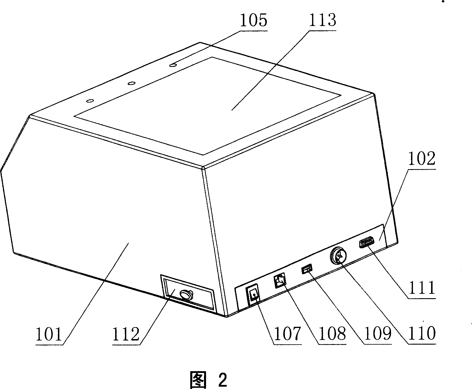
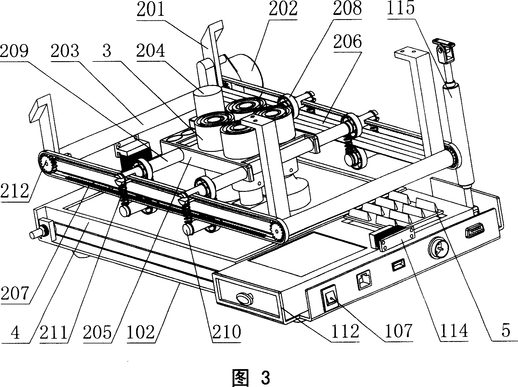
[0057] As shown in Fig. 1, Fig. 2, Fig. 3, Fig. 4, Fig. 5, Fig. 10, Fig. 16 and Fig. 19, the present invention includes a chassis device, a stamp moving device, a stamp holding device 3, a file tray device 4, and a stamp destruction Device 5, operation authority recognizer 6, projector 7, camera 8, control circuit, described chassis device comprises loam cake 101, base 102, ink pad box 112, liquid crystal display 104, voice alarm, voice indicator light 105, operation Button 106, operation status indicator light 103, hydraulic cylinder 115, interface device, the upper cover 101 and the base 102 are airtightly connected through the electromagnet lock 114, so as to prevent the upper cover 101 and the base 102 from being opened illegally , the stamp moving device and the stamp holding device 3 are all arranged in the space enclosed by the upper cover 101 and the base 102, and the hydraulic cylinder 115 connects the upper cover 101 and the base 102 to It is convenient to open the u...

Embodiment 2

[0063] As shown in Figure 1, Figure 2, Figure 6, Figure 7, Figure 8, Figure 11, Figure 12, Figure 17, Figure 18, and Figure 19, the differences between this embodiment and Embodiment 1 are:

[0064] Described stamp moving device comprises fixed support 201, longitudinal driving mechanism, transverse driving mechanism, mobile support 205, and described seal clamping device 3 is fixed on the described mobile support 205, and described vertical driving mechanism is connected with described fixed support 201. connected, the longitudinal drive mechanism includes a longitudinal motor 202, an I longitudinal guide rail 215, and an II longitudinal guide rail 217. The I longitudinal guide rail 215 and the II longitudinal guide rail 217 are parallel to each other and connected with the fixed bracket 201. The longitudinal The output shaft of the motor 202 is fixedly connected to the III gear 220, the I longitudinal guide rail 215 is smooth and cylindrical, the II longitudinal guide rail 21...

Embodiment 3

[0070] As shown in Fig. 1, Fig. 2, Fig. 9, Fig. 13, Fig. 14, Fig. 15, Fig. 16, and Fig. 19, the differences between this embodiment and the first embodiment are:

[0071] Described stamp moving device comprises fixed support 201, longitudinal driving mechanism, transverse driving mechanism, mobile support 205, and described seal clamping device 3 is fixed on the described mobile support 205, and described vertical driving mechanism is connected with described fixed support 201. connected, the longitudinal drive mechanism includes a longitudinal motor 202, an I longitudinal guide rail 215, and a longitudinal lead screw 227, and the I longitudinal guide rail 215 and the longitudinal lead screw 227 are parallel to each other and connected with the fixed bracket 201, the longitudinal The motor 202 is fixedly connected to the fixed bracket 201, the output shaft of the longitudinal motor 202 is fixedly connected to the longitudinal lead screw 227, and the transverse drive mechanism i...


PUM


Abstract

A remote network seal-affixing device able to automatically affix seal under the control of remote signal and with high safety is composed of a box consisting of upper cover, main body, hydraulic cylinder, interface and electromagnetic lock, a sealing moving unit, a sealing holder, a document bearing tray, a seal destroyer, a recognizer, a projector, a camera head, and a control circuit.

Description

technical field [0001] The invention relates to a remote network seal machine. Background technique [0002] About half of the countries in the world use seals as legal confirmation marks, and China is one of them. In daily social and economic activities, many contracts, bills and other documents need to be affixed with various seals, and with the development of human economic activities and society, seals are becoming more and more important. However, the current ineffective management of seals gives many lawbreakers opportunities to take advantage of, resulting in economic crimes. Many major economic cases have an important relationship with the illegal use of seals, and some are even the main reason. At present, the process of affixing a seal mostly adopts the traditional manual method of stamping with force. This traditional method of affixing the seal is likely to cause the seal to be unclear due to uneven force and uneven distribution of th...

Claims


Application Information

Patent Timeline
IPC IPC(8): B41K3/00B41K3/62
Inventor 张立安
Owner 张立安
Learn More