
A diversion cooling device

A technology of diversion device, diversion and heat dissipation, applied in cooling/ventilation/heating renovation, electrical components, electrical equipment structural parts, etc. Achieve the effect of solving heat accumulation, ensuring effective operation and effective heat dissipation

Active Publication Date: 2020-04-03
GUANGDONG VTRON TECH CO LTD
View PDF8 Cites 0 Cited by
  • Summary
  • Abstract
  • Description
  • Claims
  • Application Information

AI Technical Summary

Problems solved by technology

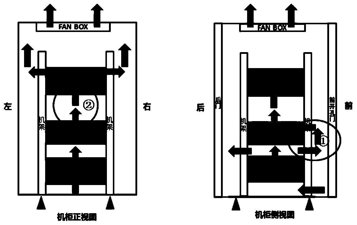
[0003] When processor devices with different air duct forms are placed in the cabinet for combined application, the air ducts are intricate, and the air outlet from the lower equipment often affects the air intake from the upper equipment (such as figure 2 shown in ① and ②), which will worsen the air intake environment of the upper equipment
The higher the temperature of the air inlet environment, the serious impact on the reliability of the business chips and power devices on the equipment boards. Research shows that the failure rate will increase by 10% when the chip junction temperature rises by 1 degree

Method used


Image

  • A diversion cooling device
  • A diversion cooling device
  • A diversion cooling device

Examples


Embodiment Construction

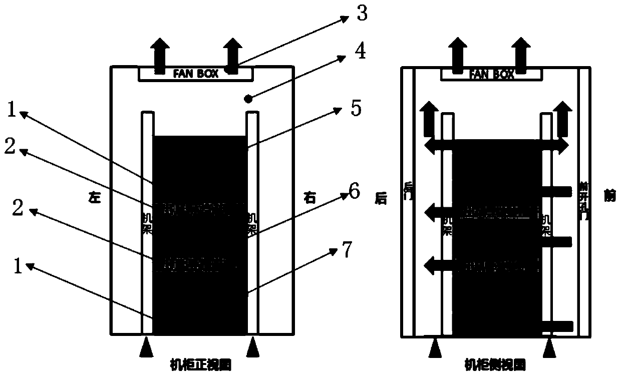
[0024] An embodiment of the present invention provides a flow guide and heat dissipation device, which solves the technical problem of heat accumulation between devices in a cabinet.

[0025] In order to make the purpose, features and advantages of the present invention more obvious and understandable, the technical solutions in the embodiments of the present invention will be clearly and completely described below in conjunction with the accompanying drawings in the embodiments of the present invention. Obviously, the following The described embodiments are only some, not all, embodiments of the present invention. Based on the embodiments of the present invention, all other embodiments obtained by persons of ordinary skill in the art without making creative efforts belong to the protection scope of the present invention.

[0026] see figure 1 , an embodiment of a conduction heat dissipation device provided in an embodiment of the present invention includes:

[0027] Such a...


PUM


Abstract

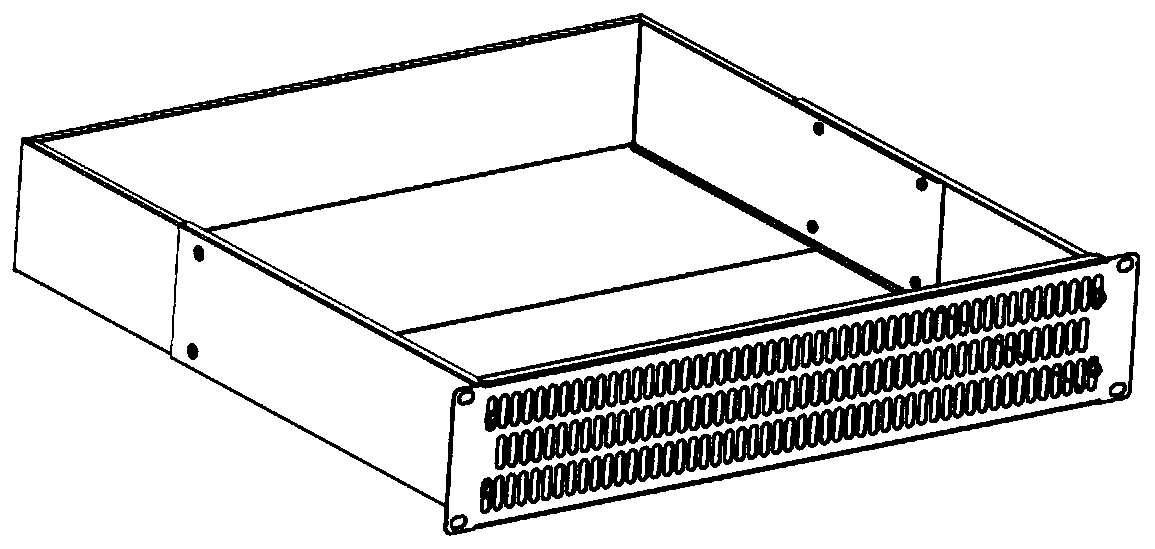
The embodiment of the invention discloses a flow guide and heat dissipation device, which is used to solve the technical problem of heat accumulation between devices in a cabinet. An air guide and heat dissipation device according to an embodiment of the present invention includes: an air inlet guide device, an air outlet guide device, and a fan module; the air inlet guide device and the air outlet guide device are installed in the cabinet through hanging ears on the square hole bar; the device is installed on the square hole bar of the corresponding cabinet through the hanging ears; the fan module is installed on the top of the cabinet.

Description

technical field [0001] The invention relates to the field of heat dissipation, in particular to a flow guiding heat dissipation device. Background technique [0002] At present, processor equipment is widely used in the visualization industry, and its main function is the input, conversion processing and output of images and video signals. Due to the diversification of customer needs and application scenarios, the form of processor equipment is also diversified, and the air ducts at the thermal design level are also diversified, such as: upper and lower air ducts, left and right air ducts, front and rear air ducts, etc. [0003] When processor devices with different air duct forms are placed in the cabinet for combined application, the air ducts are intricate, and the air outlet from the lower equipment often affects the air intake from the upper equipment (such as figure 2 ① and ② in the middle), and then worsen the air intake environment of the upper equipment. The highe...

Claims


Application Information

Patent Timeline
Patent Type & Authority Patents(China)
IPC IPC(8): H05K7/20
CPCH05K7/20145H05K7/20172
Inventor 孙盼盼
Owner GUANGDONG VTRON TECH CO LTD
Learn More