Supercharge Your Innovation With Domain-Expert AI Agents!

stent graft

A stent-graft and support segment technology, applied in stents, drug devices, other medical devices, etc., can solve problems such as space narrowing, affecting the abdominal aorta, and affecting the blood flow supply of aortic stents.

Active Publication Date: 2019-12-10
LIFETECH SCIENTIFIC (SHENZHEN) CO LTD
View PDF8 Cites 0 Cited by
  • Summary
  • Abstract
  • Description
  • Claims
  • Application Information

AI Technical Summary

Problems solved by technology

[0006] However, when the radial recess distance of the recessed portion along the aortic stent vessel is large, although a large space is reserved to facilitate the implantation of the branch stent, the space corresponding to the recessed portion of the aortic stent vessel changes accordingly. Therefore, the blood flow supply of the aortic stent will inevitably be affected, which will spread to the brachiocephalic trunk and abdominal aorta, causing corresponding complications

Method used


Image

  • stent graft
  • stent graft
  • stent graft

Examples


Embodiment 1

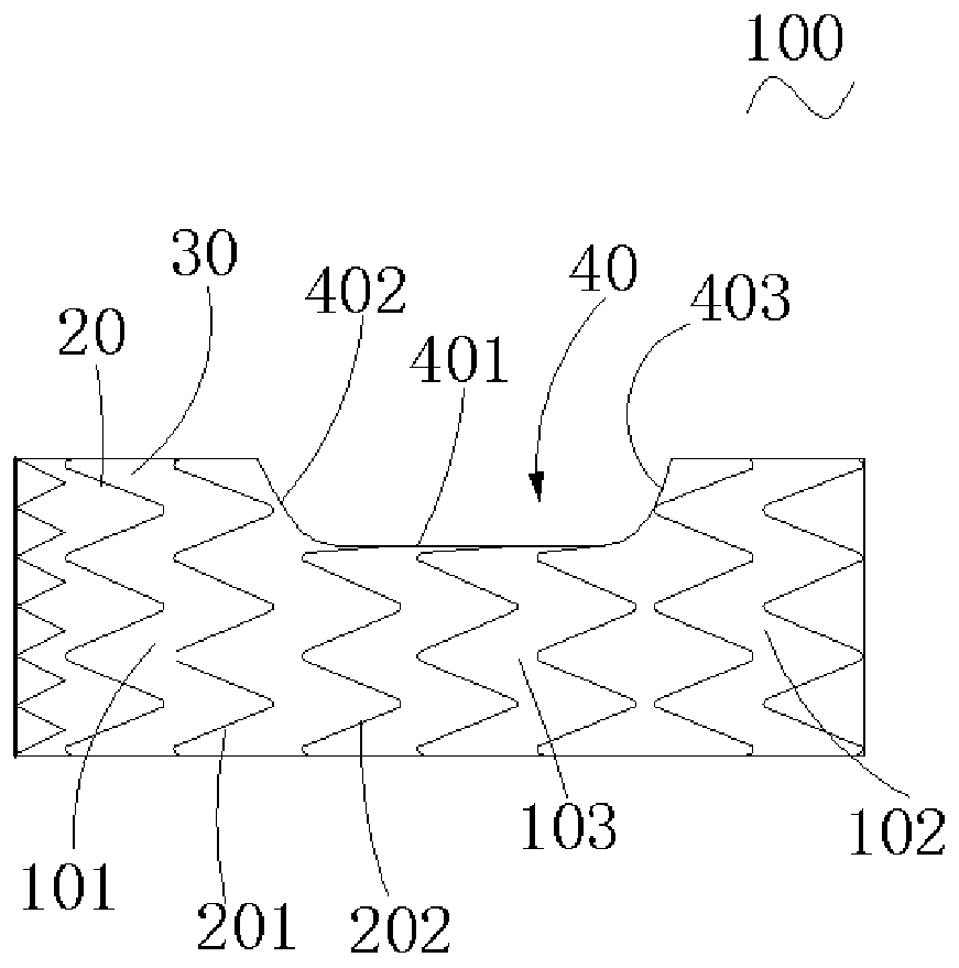
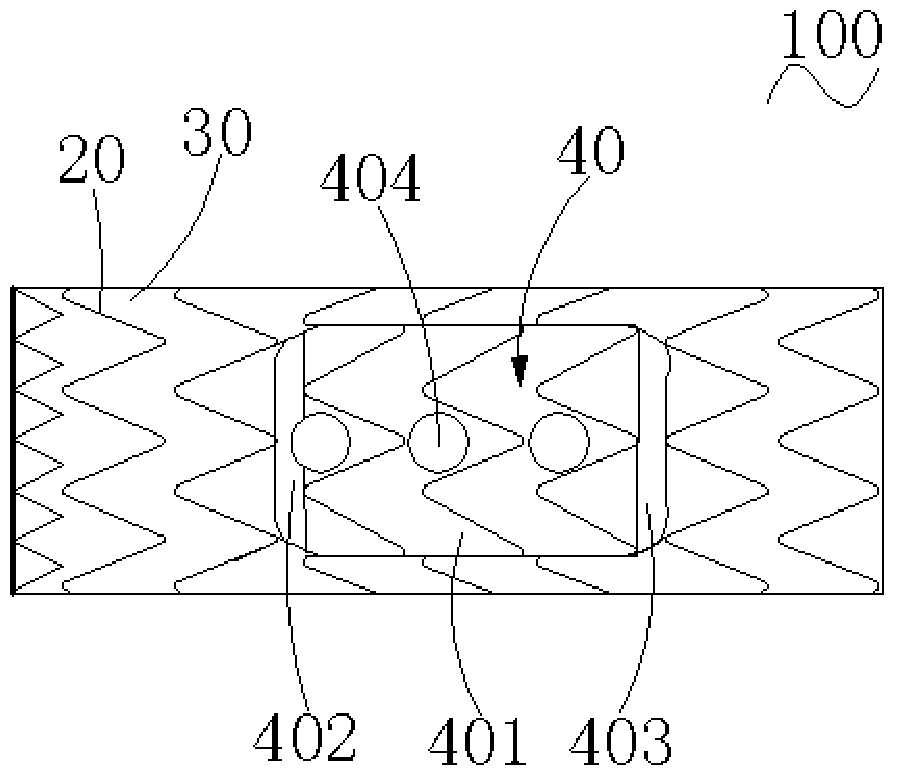
[0045] Referring to Fig. 2 (a) to Fig. 2 (d), the stent graft 100 comprises a bare stent 20 and a membrane 30 covered on the surface of the bare stent 20, along the length direction of the stent graft 100, the stent graft 100 comprises a proximal end The supporting section 101 , the distal supporting section 102 and the recessed section 103 located between the proximal supporting section 101 and the distal supporting section 102 and connected to the proximal supporting section 101 and the distal supporting section 102 respectively. The concave section 103 includes a concave portion 40 that is concave toward a direction close to the longitudinal central axis of the stent graft 100 . Three through holes 404 are also opened on the covering film 30 in the recessed part 40 , through which the blood flow can flow into the recessed part 40 from the lumen of the stent graft 100 through the through holes 404 , and further flow into each through hole 404 of the recessed part 40 correspo...

Embodiment 2

[0073] Please refer to FIG. 9(a) to FIG. 9(d), the structure of the stent-graft in Example 2 is substantially the same as that of the stent-graft 100 in Example 1, the only difference is that the support 203d of the bare stent 20d and the The supporting member 203 of Embodiment 1 is different.

[0074] In this embodiment, the bare stent 20d includes two sets of support members 203d separated from each other. Each set of support members 203d includes a proximal bent portion 2031d and a distal bent portion 2033d that are separated from each other. The shape and structure of the proximal bending portion 2031d and the distal bending portion 2033d are the same as those of the proximal bending portion 2031 and the distal bending portion 2033 in Embodiment 1, respectively. The only difference is that the proximal bending portion 2031d and the distal bending portion 2033d are not connected by a straight line.

[0075] When the stent-graft of this embodiment is implanted in the body ...

Embodiment 3

[0077] Please refer to Fig. 10(a)-Fig. 10(e), the structure of the stent-graft in Example 3 is roughly the same as that of the stent-graft 100 in Example 1, the difference lies in the support member of the bare stent 20e in Example 3 The structure of 203e is different from that of the supporting member 203 in the first embodiment.

[0078] In this embodiment, the plurality of waves of the protruding second wave-shaped ring 202e of the first round of the proximal first wave-shaped ring 201e are bent toward the bottom surface 401'e of the concave structure 40'e, and the bent waves The proximal bent portion 2031e of the support member 203e is partially formed. Specifically, the support body of the plurality of waveforms of the first round of proximal first waveform ring 201e is bent, and bends together with the distal vertices of the plurality of waveforms towards the bottom surface 401'e. Similarly, the plurality of waves of the protruding second wave-shaped ring 202e of the fi...


PUM


Abstract

The invention relates to a covered stent. The stent comprises a near-end support section, a far-end support section and a recessed section. The recessed section comprises a recessed part recessed close to a vertical center shaft of the covered stent. The recessed part is provided with at least one through hole used for inserting branch stents and comprises a bottom surface, a near-end peripheral surface and a far-end peripheral surface. The recessed part further comprises at least one group of support parts comprising near-end bent parts arranged on the near-end peripheral surface and far-end bent parts arranged on the far-end peripheral surface. The covered stent has the following beneficial effects: when the covered stent is implanted into a body and the recessed part bends towards the arch bend of the aorta, no deformation or smaller deformation occurs on the near-end peripheral surface and the far-end peripheral surface of the recessed part so that the distance between the bottom surface of the recessed part and a blood pipe wall is ensured; therefore, blood flows can flow through a pipe cavity of the covered stent through the through holes into the recessed part and flow into branch blood vessels; and therefore, the branch stents can smoothly flow through the through holes and corresponding branch blood vessels.

Description

technical field [0001] The invention relates to the technical field of interventional medical devices, in particular to a covered stent for implanting a thoracic aorta. Background technique [0002] With the sharp increase in the incidence of hypertension, the incidence of arterial-related diseases has increased significantly, and is expected to increase at a rate of more than 40% in the next 5 to 7 years. Among them, acute Stanford type A aortic dissection (acute aortic dissection type A, referred to as AADA) is the most common and dangerous aortic emergency in the field of cardiovascular surgery. If left untreated, the mortality rate of AADA one week after onset is as high as 50-91%. If only conservative medical treatment is received, the 24-hour mortality rate can reach 20%, and the 48-hour mortality rate can reach 30%. Therefore, once AADA is diagnosed, emergency surgical intervention is necessary if there are no surgical contraindications. However, even under modern m...

Claims


Application Information

Patent Timeline
Patent Type & Authority Patents(China)
IPC IPC(8): A61F2/90A61F2/856A61M31/00
CPCA61F2/856A61F2/90A61M31/00
Inventor 肖本好刘彩萍
Owner LIFETECH SCIENTIFIC (SHENZHEN) CO LTD
Features
  • R&D
  • Intellectual Property
  • Life Sciences
  • Materials
  • Tech Scout
  • Unparalleled Data Quality
  • Higher Quality Content
  • 60% Fewer Hallucinations
Learn More