
Pressure release nozzle applied to filtering machine

A filter and nozzle technology, applied in the direction of injection device, injection device, etc., can solve the problems of increased production cost, large maintenance cost, cumbersome adjustment, etc., and achieve the effects of convenient cleaning, avoiding bursting, and simple structure

Inactive Publication Date: 2017-07-07
DONGGUAN JIAQIAN NEW MATERIAL TECH CO LTD
View PDF5 Cites 1 Cited by
  • Summary
  • Abstract
  • Description
  • Claims
  • Application Information

AI Technical Summary

Problems solved by technology

At present, the water flow rate of the nozzle in the horizontal vacuum filter for solid-liquid separation can only be controlled by a regulating valve, which is cumbersome to adjust and will increase production costs
In addition, after the existing nozzle is worn out, the entire nozzle needs to be removed and replaced with a new one, which will undoubtedly bring about a large maintenance cost

Method used


Image

  • Pressure release nozzle applied to filtering machine
  • Pressure release nozzle applied to filtering machine
  • Pressure release nozzle applied to filtering machine

Examples


Embodiment Construction

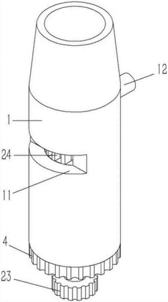
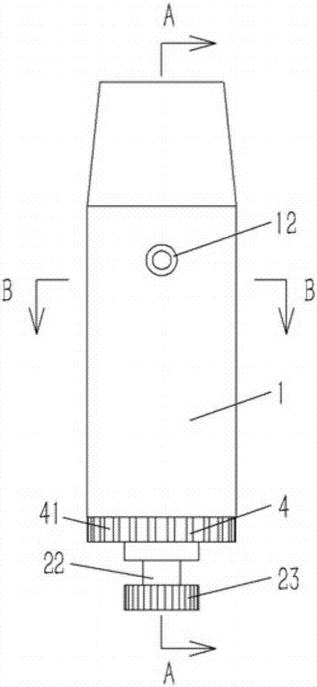
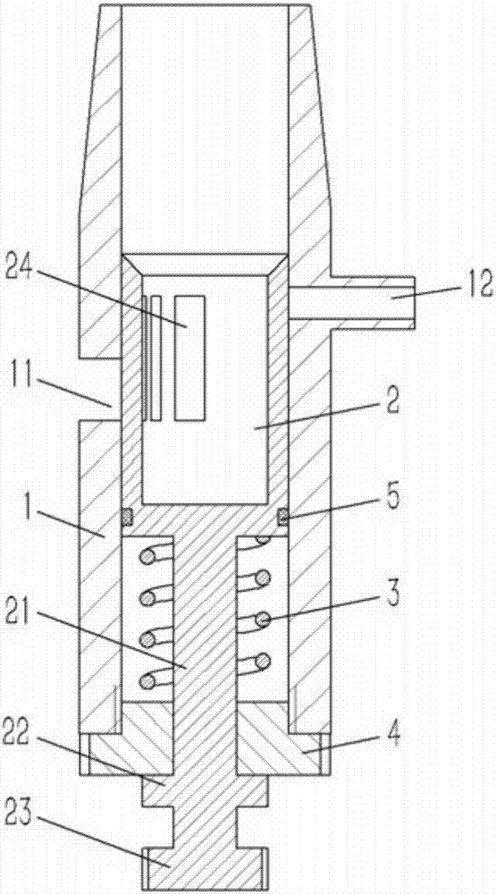
[0025] Example: see Figures 1 to 4 As shown, a pressure relief nozzle applied to a filter includes a nozzle pipe 1, a water outlet 11 is formed on the side wall of the nozzle pipe 1, an annular valve seat 2 is inserted into the nozzle pipe 1, and a valve seat 2 is formed on the nozzle pipe 1. There are several water outlet grooves 24 with different widths. The water outlet grooves 24 are opposite to the water outlet 11 on the nozzle pipe 1. A pressure relief pipe 12 is formed on the nozzle pipe 1 between the lower side of the upper end surface of the valve seat 2 and the upper side of the water outlet 11. A vertical guide post 21 is formed on the lower end surface of the valve seat 2, and the lower end of the guide post 21 passes through the "convex"-shaped end cover 4 to form a ring platform 22, which is pressed against the lower end surface of the end cover 4 Above, the end cap 4 is screwed on the bottom of the nozzle pipe 1, and the guide column 21 is inserted with a compr...


PUM


Abstract

The invention discloses a pressure release nozzle applied to a filtering machine. The pressure release nozzle comprises a nozzle pipe. A water outlet is formed in the side wall of the nozzle pipe. An annular valve seat is connected into the nozzle pipe in an inserted manner. Multiple water outlet grooves different in width are formed in the valve seat. The water outlet grooves are opposite to the water outlet in the nozzle pipe. A pressure release pipe is formed at the position, between the lower side of the upper end face of the valve seat and the upper side of the water outlet, on the nozzle pipe. A vertical guide pillar is formed on the lower end face of the valve seat. The lower end of the guide pillar penetrates an inverted-T-shaped end cover to form a ring table. The ring table abuts against the lower end face of the end cover in a pressing manner. The end cover is in screw joint to the bottom end of the nozzle pipe. The guide pillar is sleeved with a compression spring in an inserted manner. The two ends of the compression spring abut against the end cover and the valve seat correspondingly in a pressing manner. The pressure release nozzle is simple in structure, the water outlet flow of the nozzle can be mechanically adjusted conveniently, meanwhile, the nozzle can be demounted, and cleaning is convenient.

Description

[0001] Technical field: [0002] The invention relates to the technical field of chemical equipment, in particular to a pressure relief nozzle applied to a filter. [0003] Background technique: [0004] At present, the horizontal vacuum filter used in solid-liquid separation in China requires a washing device to repeatedly spray and wash the material when filtering the material. Since the washing water used for washing is process water (process water), it contains more impurities. , the nozzle is easy to block, so the water output of the nozzle needs to be adjusted. At present, the water flow rate of the nozzle in the horizontal vacuum filter for solid-liquid separation can only be controlled by a regulating valve, which is cumbersome and will increase production costs. In addition, after the existing nozzles are worn out, the entire nozzles need to be removed and replaced with new ones, which will undoubtedly bring about large maintenance costs. [0005] Invention content: ...

Claims


Application Information

Patent Timeline
Patent Type & Authority Applications(China)
IPC IPC(8): B05B1/32
CPCB05B1/326
Inventor 王海燕
Owner DONGGUAN JIAQIAN NEW MATERIAL TECH CO LTD
Learn More