Seal device for pulse valve

A technology of sealing device and pulse valve, applied in valve device, valve operation/release device, lift valve, etc., can solve the problems of valve air leakage and increased energy consumption of dust removal system, to prevent leakage, increase impact resistance, The effect of meeting the bonding strength

Inactive Publication Date: 2017-07-07
上海袋式除尘配件有限公司
View PDF7 Cites 0 Cited by
  • Summary
  • Abstract
  • Description
  • Claims
  • Application Information

AI Technical Summary

Problems solved by technology

However, due to some objective factors, the existing pulse valve often leaks during use, which increases the energy consumption of the entire dust removal system.

Method used


Image

  • Seal device for pulse valve
  • Seal device for pulse valve
  • Seal device for pulse valve

Examples


Embodiment 1

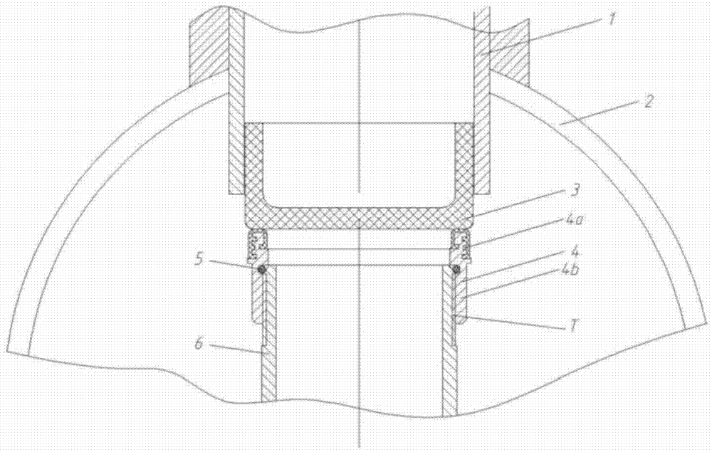
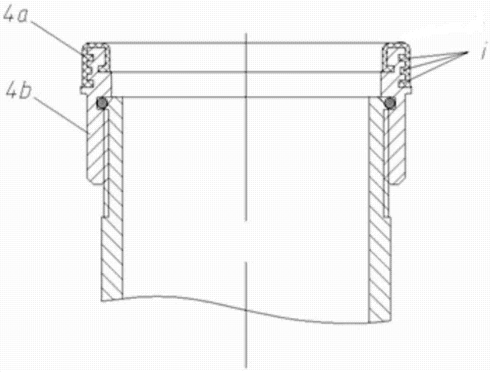
[0024] Such as figure 1 As shown, it is a schematic diagram of the installation of the sealing device 4 and the pulse valve. The pulse valve includes a valve body 1, an air bag 2 and a blowing pipe 3. The valve body 1 is installed on the air bag 2. The sealing device 4 Installed in the air bag 2 of the pulse valve. The sealing device 4 includes a vulcanized rubber layer 4a and a skeleton 4b, such as figure 2 As shown, a zigzag groove i is set above the skeleton 4b, which matches the inner wall of the vulcanized rubber layer 4a, so that the vulcanized rubber layer 4a covers the upper part of the skeleton 4b, and passes through the vulcanized rubber layer 4a and the valve flap 3 of the pulse valve. The sealing is achieved by adhering to the contact, and the skeleton 4b is fixed on the blowing pipe 6 of the pulse valve through the thread T,

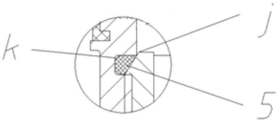
[0025] Such as image 3 As shown in the partial enlarged view of the sealing device 4, the upper end of the frame 4b is provided with a...


PUM


Abstract

The invention relates to a seal device for a pulse valve. The pulse valve comprises a valve body (1), an air pocket (2), a valve clack (3) and a blowing pipe (6), a seal device (4) is fixed to the blowing pipe (6), the valve clack (3) is tightly attached to the seal device (4), during valve opening, the position of the valve clack (3) moves upwards, and gas in the air pocket (2) is moved upwards through the valve clack (3), flows into the blowing pipe (6), through the gap between the valve clack and the seal device (4) and is sprayed out. Compared with the prior art, the soft seal manner of a vulcanized rubber assembly is adopted to replace an original single blowing pipe hard seal structure, an inner seal groove is added, and the seal property of the pulse valve is greatly increased.

Description

technical field [0001] The invention relates to the technical field of pulse valves, in particular to a sealing device for pulse valves. Background technique [0002] With the strengthening of people's awareness of environmental protection, flue gas and dust control has received extensive attention. With its excellent dust removal efficiency and low construction cost, the bag filter has received more and more attention. As an important component of the bag filter, the pulse valve used in the bag filter has become one of the key components that affect the cleaning efficiency of the entire system. Therefore, various standards and regulations for pulse valves are promulgated one after another, and the requirements for manufacturers are getting higher and higher. However, due to some objective factors, the existing pulse valve often suffers from valve leakage during use, which increases the energy consumption of the entire dust removal system. Contents of the invention [0...

Claims


Application Information

Patent Timeline
Patent Type & Authority Applications(China)
IPC IPC(8): F16K1/32F16K31/12
CPCF16K1/32F16K31/12
Inventor 黄河王超诸千根
Owner 上海袋式除尘配件有限公司
Why Eureka
Try Eureka