Apparatus for overlay error detection and measurement and calibration method

A technology of overlay error and overlay mark, which is applied in the direction of photolithography exposure device, microlithography exposure equipment, photoplate process of pattern surface, etc., can solve the problems of large overlay measurement error and low precision, and achieve Reduction of correlation and improvement of overlay measurement accuracy

Active Publication Date: 2017-07-07
SHANGHAI MICRO ELECTRONICS EQUIP (GRP) CO LTD
View PDF3 Cites 13 Cited by
  • Summary
  • Abstract
  • Description
  • Claims
  • Application Information

AI Technical Summary

Problems solved by technology

[0005] The invention provides a device and a calibration method for overlay error detection to solve the problems of large overlay measurement error and low precision in the prior art

Method used


Image

  • Apparatus for overlay error detection and measurement and calibration method
  • Apparatus for overlay error detection and measurement and calibration method
  • Apparatus for overlay error detection and measurement and calibration method

Examples


Embodiment 1

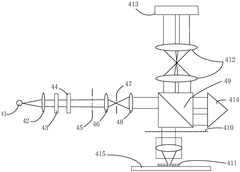
[0067] In this embodiment, the overlay mark 411 itself is used as a reference mark, and the reference mark is obtained by adding overlay signals of the overlay mark 411 at 0 and 180 degrees.

[0068] Specifically, please refer to Figure 9 , the way to obtain the reference signal is:

[0069] When the overlay mark 411 is 0 degrees, the detector 413 receives the measurement light m and the monitoring light s, and performs light intensity disturbance normalization processing on the measurement light m and the monitoring light s to obtain the overlay signal OV_0 at 0 degrees;

[0070] Next, after the rotatable workpiece table 415 drives the overlay mark 411 to rotate 180 degrees, the detector 413 receives the measurement light m and the monitoring light s again, and performs light intensity perturbation normalization processing on the measurement light m and monitoring light s to obtain Overlay signal OV_180 at 180 degrees;

[0071] Then, add the overlay signals of the overlay ...

Embodiment 2

[0080] In this embodiment, a grating mark having the same period as the overlay mark on the test silicon wafer is used as a reference mark. There are two schemes for generating reference marks; one scheme is exactly the same as that in Embodiment 1, and the grating marks on the test silicon wafer are overlaid with signals at 0 degrees and 180 degrees, and added. Another solution is: directly collect the diffraction signal of the grating mark at 0 degrees and perform normalization to obtain the reference signal.

Embodiment 3

[0082] The reference mark in this embodiment uses the grating reference plate installed on the workpiece table. The beam reference plate has grating marks with the same period and direction as the overlay mark, and collects corresponding diffracted light signals according to the difference between the overlay marks. The signal obtained after normalization is the reference signal.


PUM


Abstract

The invention discloses an apparatus for overlay error detection and a measurement and calibration method. The apparatus comprises a light source, an illuminating system, an objective lens, a reference mark, a detector, and a rotatable workpiece table, wherein the light source is used for generating incident light; the incident light is scattered light; the illuminating system is used for dividing the incident light into two beams, wherein one beam is used as measurement light to come into the objective lens while the other beam is used as monitoring light to come into the detector; the objective lens is used for enabling the measured light to come into an overlay mark in an inclined manner; the reference mark is used for generating reference light; the detector is positioned on the pupil plane of the objective lens and used for detecting diffraction spectrum of the overlay mark; and the rotatable workpiece table is used for bearing and rotating the reference mark and / or the overlay mark. The reference light, which passes through the light path that is totally the same as that of the overlay signal, is adopted for performing measurement signal normalization, so as to eliminate influence on the overlay signal from asymmetry of transmittance, space distribution non-uniformity of the incident light, space distribution changes, sensitivity non-uniformity of the detector, and the like; and a similar measurement and calibration scheme is never mentioned in the prior art.

Description

technical field [0001] The invention relates to the field of integrated circuit manufacturing, in particular to a device and a calibration method for overlay error detection. Background technique [0002] According to the lithography measurement technology roadmap given by ITRS, as the CD size of lithography patterns enters the process node of 22nm and below, especially the wide application of double patterning technology, the overlay of lithography process parameters Measurement accuracy requirements have moved into the sub-nanometer realm. Due to the limitation of imaging resolution limit, the traditional overlay measurement technology based on imaging and image recognition (English full name: Imaging-Based overlay, abbreviation: IBO) has gradually been unable to meet the requirements of new process nodes for overlay measurement. The overlay measurement technique based on diffracted light detection (English full name: Diffraction-Based overlay, abbreviation: DBO) is gradu...

Claims


Application Information

Patent Timeline
Patent Type & Authority Applications(China)
IPC IPC(8): G03F7/20G03F9/00
CPCG03F7/70633G03F9/7046G03F9/7069G03F9/7088
Inventor 彭博方陆海亮王帆
Owner SHANGHAI MICRO ELECTRONICS EQUIP (GRP) CO LTD
Why Eureka
Try Eureka