Stable welding device

A welding device and stable technology, applied in the field of stable welding devices, can solve problems such as electric shock for users, inconvenient welding work, and easy generation of arcs, etc., to achieve the effects of preventing electric shock accidents, reducing operating steps, and improving work efficiency

Active Publication Date: 2017-07-14
晖腾工业科技有限公司
View PDF6 Cites 1 Cited by
  • Summary
  • Abstract
  • Description
  • Claims
  • Application Information

AI Technical Summary

Problems solved by technology

[0002] At present, welding machines are used more and more widely, and they rely on the power supply connection to work normally. Therefore, whether the power supply connection of the welding machine is stable and the safety of the power supply connection is the basis for determining whether the welding machine can work normally. The voltage required by the machine is relatively high, and it is easily affected by the voltage when plugging and unplugging, and it is easy to generate an arc. The generation of the arc is likely to cause an electric shock to the user, and the protection ability is poor. The power supply mode of the electric welding machine is plug-in, which is easy to be affected by external factors such as dragging and pulling, making the plug-in loose, resulting in poor contact, and causing inconvenience to the welding work

Method used


Image

  • Stable welding device
  • Stable welding device
  • Stable welding device

Examples


Embodiment Construction

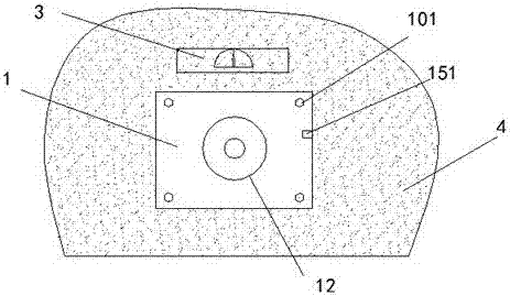
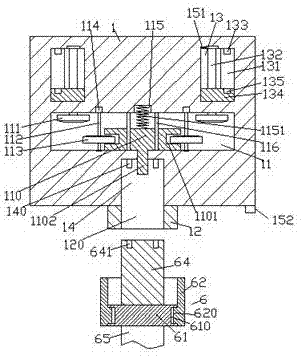
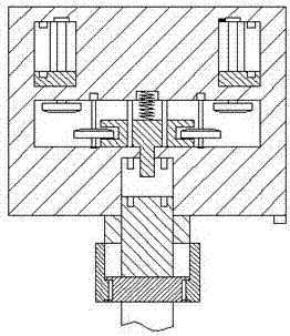
[0021] Such as Figure 1-Figure 6 As shown, a stable welding device of the present invention includes a power distribution base 1 and a fastening part 6, the power distribution base 1 is fixed on the wall 4 by bolts 101, and the power distribution base 1 above the The front end of the wall 4 is provided with a voltage converter 3, the voltage converter 3 is electrically connected to the power distribution base 1 through a line, and the voltage converter 3 is used to convert the output voltage of the power distribution base 1, thereby To meet the power connection requirements of electric welding machines with different powers, an external threaded part 12 is provided at the center of the front end of the power distribution base 1, and a threaded part 12 is provided inside the threaded part 12. The power distribution seat 1 on the side is provided with a fastening hole 14, and the inner wall of the rear side of the fastening hole 14 is provided with a second insert piece 140, an...


PUM


Abstract

The invention discloses a stable welding device which comprises a distribution seat and a tight insertion part. The distribution seat is fixed to the wall through a bolt. A voltage converter is arranged on the part, above the distribution seat, of the front end face of the wall. The voltage converter is electrically connected with the distribution seat through a line. An external threaded part is arranged on the front end face of the distribution seat. A through groove is formed in the external threaded part, and a tight insertion hole is formed in the position, on the rear side of the through hole, in the distribution seat. A second insertion piece is arranged on the inner wall of the rear side of the tight insertion hole. A first containing cavity is formed in the position, behind the tight insertion hole, in the distribution seat. A containing groove is formed in the inner wall of the rear side of the first containing cavity. A push block is arranged at the position, on the front side of the containing groove, in the first containing cavity. A compression spring is arranged between the end face of the rear side of the push block and the containing groove, sliding rods are symmetrically arranged at the positions, on the two sides of the compression spring, in the first containing cavity, and the sliding rods are matched and connected with the push block in a sliding manner. The stable welding device is simple in structure, convenient to operate, stable in power supply connection and capable of preventing the phenomenon that electric arcs are generated during inserting and pulling, and consequently electric shock accidents happen, and power supply safety and stability are improved.

Description

technical field [0001] The invention relates to the technical field of welding, in particular to a stable welding device. Background technique [0002] At present, welding machines are used more and more widely, and they rely on the power supply connection to work normally. Therefore, whether the power supply connection of the welding machine is stable and the safety of the power supply connection is the basis for determining whether the welding machine can work normally. The voltage required by the machine is relatively high, and it is easily affected by the voltage when plugging and unplugging, and it is easy to generate an arc. The generation of the arc is likely to cause an electric shock to the user. The power supply mode of the electric welding machine is plug-in, which is easy to be affected by external factors such as dragging and pulling, which will make the plug-in loose, cause poor contact, and bring inconvenience to the welding work. Contents of the invention ...

Claims


Application Information

Patent Timeline
Patent Type & Authority Applications(China)
IPC IPC(8): B23K37/00
CPCB23K37/00
Inventor 蒋妙海
Owner 晖腾工业科技有限公司
Why Eureka
Try Eureka