
Multifunctional cleaning cart for transit bus

A multi-functional, bus technology, applied to multi-axis trolleys, in-vehicle cleaning devices, trolleys, etc., can solve the problem of inconvenient cleaning of buses, and achieve the effect of saving labor and improving work efficiency

Inactive Publication Date: 2017-07-14
翁帆安
View PDF0 Cites 11 Cited by
  • Summary
  • Abstract
  • Description
  • Claims
  • Application Information

AI Technical Summary

Problems solved by technology

[0005] In order to overcome the inconvenient shortcomings of spraying disinfectant in the bus and cleaning the bus in the prior art, the technical problem to be solved by the present invention is to provide a bus that can conveniently spray disinfectant and clean the ground. Multifunctional Cleaning Cart

Method used


Image

  • Multifunctional cleaning cart for transit bus
  • Multifunctional cleaning cart for transit bus
  • Multifunctional cleaning cart for transit bus

Examples


Embodiment 1

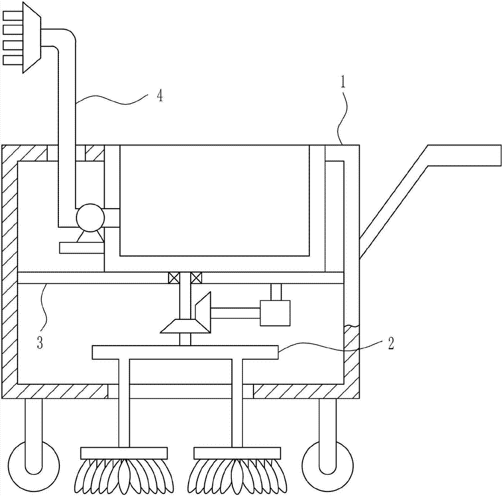
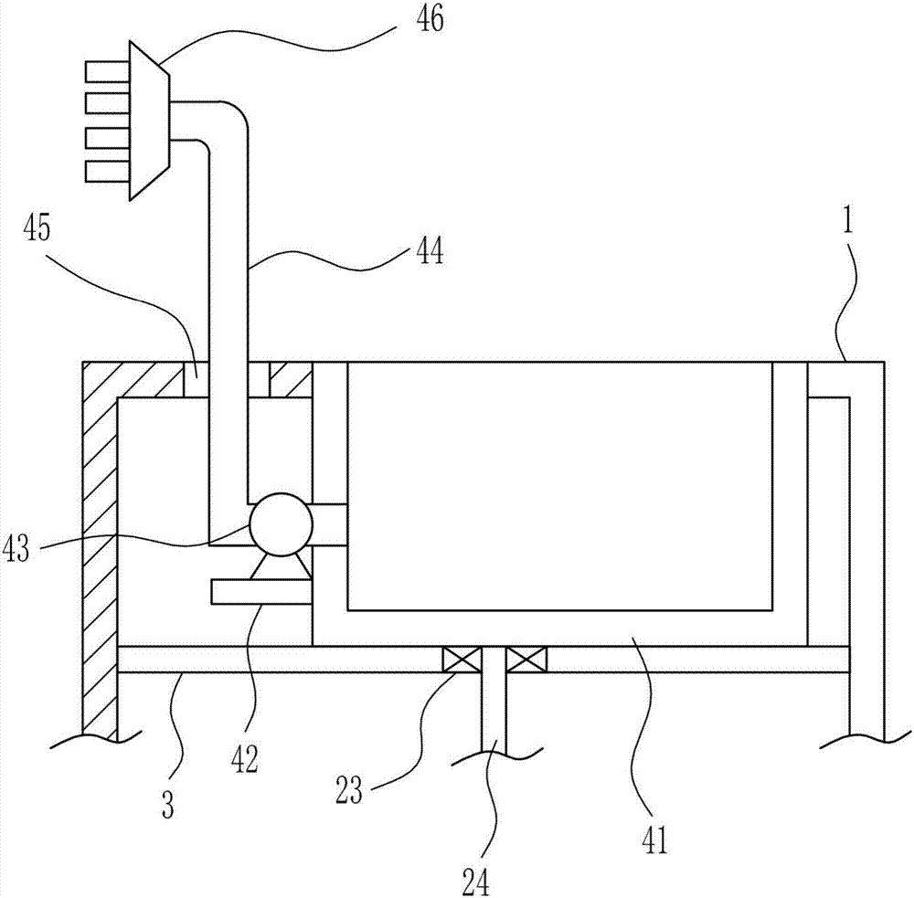
[0038] A kind of multifunctional cleaning trolley for bus, such as Figure 1-7 As shown, it includes a trolley 1, a cleaning device 2, a partition 3 and a spraying device 4, the middle part of the cart 1 is connected with a partition 3, the bottom of the partition 3 is provided with a cleaning device 2, and the top of the partition 3 Spraying device 4 is provided.

Embodiment 2

[0040] A kind of multifunctional cleaning trolley for bus, such as Figure 1-7 As shown, it includes a trolley 1, a cleaning device 2, a partition 3 and a spraying device 4, the middle part of the cart 1 is connected with a partition 3, the bottom of the partition 3 is provided with a cleaning device 2, and the top of the partition 3 Spraying device 4 is provided.

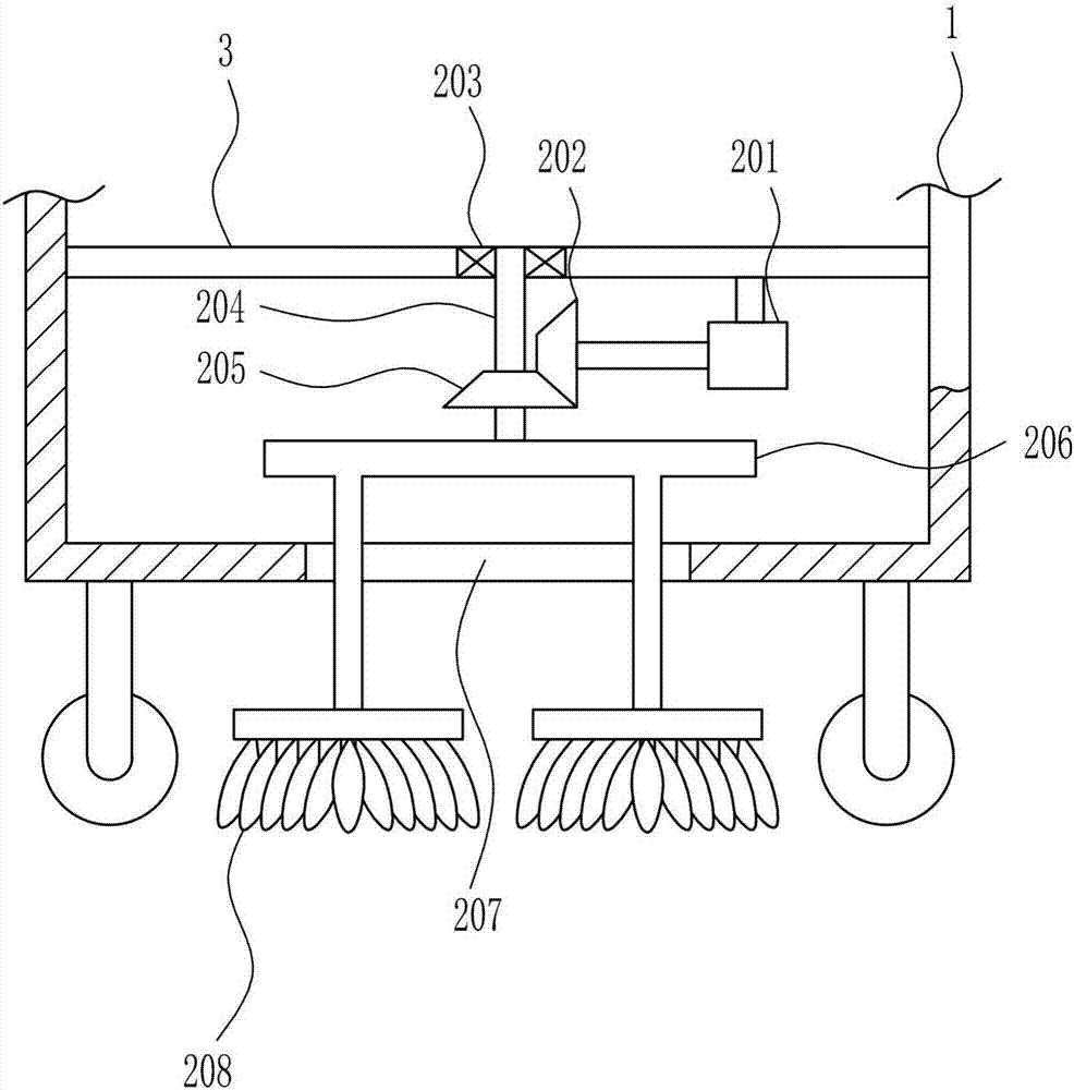
[0041] The cleaning device 2 includes a motor 201, a first bevel gear 202, a first bearing seat 203, a first rotating rod 204, a second bevel gear 205, a support 206 and a broom 208, and the bottom right side of the dividing plate 3 is connected with a motor 201, The left end of the output shaft of the motor 201 is connected with the first bevel gear 202, the middle part of the partition plate 3 is connected with the first bearing seat 203, the first bearing seat 203 is connected with the first rotating rod 204, and the bottom of the first rotating rod 204 is connected with the first rotating rod 204. Two bevel ge...

Embodiment 3

[0043] A kind of multifunctional cleaning trolley for bus, such as Figure 1-7 As shown, it includes a trolley 1, a cleaning device 2, a partition 3 and a spraying device 4, the middle part of the cart 1 is connected with a partition 3, the bottom of the partition 3 is provided with a cleaning device 2, and the top of the partition 3 Spraying device 4 is provided.

[0044] The cleaning device 2 includes a motor 201, a first bevel gear 202, a first bearing seat 203, a first rotating rod 204, a second bevel gear 205, a support 206 and a broom 208, and the bottom right side of the dividing plate 3 is connected with a motor 201, The left end of the output shaft of the motor 201 is connected with the first bevel gear 202, the middle part of the partition plate 3 is connected with the first bearing seat 203, the first bearing seat 203 is connected with the first rotating rod 204, and the bottom of the first rotating rod 204 is connected with the first rotating rod 204. Two bevel ge...


PUM


Abstract

The invention relates to a complex cleaning trolley, in particular to a multifunctional cleaning trolley for buses. The technical problem to be solved by the present invention is to provide a multifunctional cleaning trolley for buses that can conveniently spray disinfectant and clean the ground. In order to solve the above-mentioned technical problems, the present invention provides such a multifunctional cleaning trolley for buses, which includes a trolley, a cleaning device, a partition plate and a spraying device, etc.; There is a cleaning device under the board, and a spraying device above the partition board. The present invention pours the disinfectant into the charging box first and then covers the box door to prevent dust from entering the charging box, then pushes the trolley into the bus, starts the motor and the disinfectant pump at the same time, and pushes the cart car time.

Description

technical field [0001] The invention relates to a complex cleaning trolley, in particular to a multifunctional cleaning trolley for buses. Background technique [0002] Buses, city buses, that is, buses or coaches, are typical models of large and medium-sized passenger cars in the passenger car category, and are commercial vehicles designed and equipped for urban and suburban transportation. From the point of view of design and technical characteristics, buses are different from other large and medium-sized passenger vehicles (such as long-distance buses, tourist buses, group buses, etc.), this vehicle is equipped with passenger seats and passages for passengers to stand and walk. It is required to have a large standing area, wide passages and entrances and exits in the compartment, more than two doors, and low pedals. [0003] Now the bus needs regular cleaning and disinfection, and now cleaning requires manual cleaning of the ground and artificial spraying of disinfectant...

Claims


Application Information

Patent Timeline
IPC IPC(8): B60S1/64B60S3/00B62B3/02
CPCB60S1/64B60S3/008B62B3/02
Inventor 翁帆安
Owner 翁帆安
Learn More