A lift with a separate lifting device and its working method

The technology of a lifting device and working method, applied in the field of lifts, can solve the problems of being unable to correspond to different types of cars of different sizes at the same time, the single function of the lift, and the single model of the lift, etc., and achieve strong grip , The use process is intelligent, and the effect of ensuring aesthetics

Active Publication Date: 2019-06-18
赛埃孚汽车保修设备(太仓)有限公司
View PDF6 Cites 0 Cited by
  • Summary
  • Abstract
  • Description
  • Claims
  • Application Information

AI Technical Summary

Problems solved by technology

[0003] At present, the lift has a single function and cannot be moved. For the situation where the faulty vehicle cannot drive, it needs to be towed to the lift station first, which is time-consuming and laborious. In addition, the current lift has a single model and cannot simultaneously correspond to different types, different size cars

Method used


Image

  • A lift with a separate lifting device and its working method
  • A lift with a separate lifting device and its working method
  • A lift with a separate lifting device and its working method

Examples


Embodiment 1

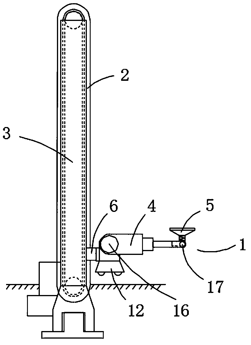
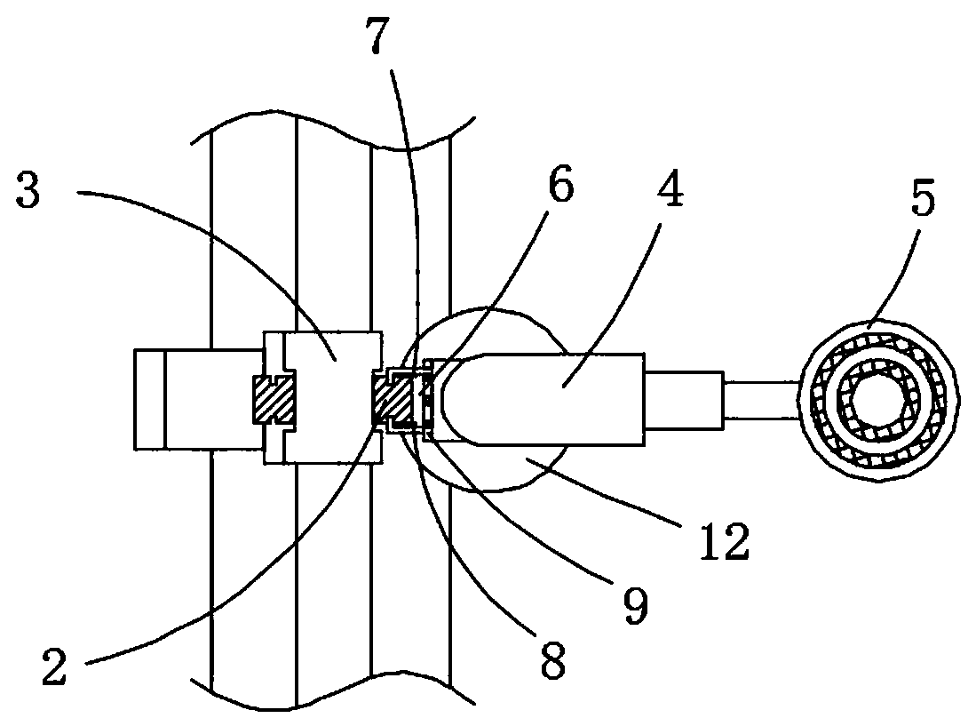
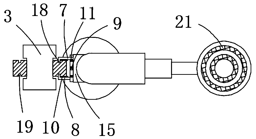
[0030] A kind of lifting machine with separate lifting device of the present invention, such as Figure 1 to Figure 6 As shown, it includes a group of lifting devices 1 working independently, and a group of columns 3 provided with a first lifting system 2, wherein the lifting device 1 includes an independent control module, a second lifting system 4, a grabbing device 5 and The docking device 6; the docking device 6 is connected or separated from the mobile pair of the first lifting system 2 through the control of the control module; the docking device 6 includes a set of oppositely arranged first clamping arms 7 and second clamping arms 8, A clamp arm driving device 9 that drives the opening and closing of the first clamp arm 7 and the second clamp arm 8 is connected with the control module. The ends of the first clamp arm 7 and the second clamp arm 8 are respectively provided with friction plates 10, and the first clamp arm 7 and the second clamp arm 8 clamp the moving pair ...

Embodiment 2

[0049] Such as Figure 7 As shown, the ends of the first clamping arm 7 and the second clamping arm 8 are respectively provided with an electromagnetic device 25, and the electromagnetic device 25 is connected to the control module; the first clamping arm 7 and the second clamping arm 8 clamp and move up and down pair, the moving pair is a chain transmission system, including a transmission chain and a sprocket, and the transmission chain is a moving pair. This structure has stable transmission, reliable structure, strong bearing capacity and flexible lifting; the grabbing device 5 is an air-pumping suction cup device.

[0050] It also includes a remote control system connected to each lifting device 1, the remote control system is respectively connected with the control module of each lifting device 1, and is provided with an operation interface to perform independent or combined operations on all lifting devices 1. manipulation.

[0051] Other structures are the same as in...


PUM


Abstract

The invention discloses a lifting machine with a separating type supporting device. The lifting machine comprises the supporting device working independently and a stand column provided with a first lifting system, wherein the supporting device comprises an independent control module, a second lifting system, a grabbing device and a butt joint device; the butt joint device is controlled by the control module to be connected or disconnected with a movement pair of the first lifting system; and the butt joint device comprises a first clamping arm and a second clamping arm which are oppositely arranged and further comprises a clamping arm driving device for driving the first clamping arm and the second clamping arm to be opened or closed, and the clamping arm driving device is connected with the control module. The supporting device can serve as a small lifting machine to be independently used, can be in automatic butt joint with the stand column, and can be combined into a large lifting machine; the using method is flexible and variable, the using process is more intelligent, the lifting machine is suitable for most vehicle types, and the lifting machine can be particularly used for over-length truck supporting.

Description

technical field [0001] The invention relates to the technical field of automobile lifts, in particular to a lift with a separate lifting device. Background technique [0002] The car lift is a device used for lifting the car in the process of car maintenance. When the car is driven to the lift station, the car can be lifted to a certain height through manual operation, which is convenient for car maintenance. Lifts play a very important role in car repair and maintenance. Now the repair shops are equipped with lifts, which are essential equipment for car repair shops. [0003] At present, the lift has a single function and cannot be moved. For the situation where the faulty vehicle cannot drive, it needs to be towed to the lift station first, which is time-consuming and laborious. In addition, the current lift has a single model and cannot simultaneously correspond to different types, Cars of different sizes. Contents of the invention [0004] Purpose of the invention: T...

Claims


Application Information

Patent Timeline
Patent Type & Authority Patents(China)
IPC IPC(8): B66F7/00
CPCB66F7/00
Inventor 陈佳媛车景辉
Owner 赛埃孚汽车保修设备(太仓)有限公司
Why Eureka
Try Eureka