Linkage type handle automatic resetting and idling device

A technology of automatic reset and idling device, which is applied in the field of anti-theft locks, can solve the problems of not describing the automatic reset feature of the handle at the same time, the failure of the automatic reset device, and the failure of the key to be drawn out, etc., to meet the convenience of the product, the structure is simple, and the satisfaction safety effect

Active Publication Date: 2017-07-14
重庆山渝道科技有限公司
View PDF13 Cites 3 Cited by
  • Summary
  • Abstract
  • Description
  • Claims
  • Application Information

AI Technical Summary

Problems solved by technology

Among them, all the above-mentioned patent applications do not mention the automatic reset of the handle. The actual operation method and existing problems are: after the handle is pressed down to unlock, the handle needs to be manually rotated to reset to a near-horizontal position, otherwise the key cannot be pulled out; After the anti-lift handle is locked, it is necessary to manually rotate the handle to reset. Although it is very light, if it is not reset, the handle will stop in an upward direction, which will affect the appearance
In this case, if only the automatic reset technology in the forward and reverse directions of the ordinary handle is used, the automatic reset device will fail after the handle is idling.
In addition, there are also patented products in the prior art that provide idling handles, such as "Overload Protector for New Intelligent Anti-theft Lock" (Patent No. 2015206788831). An overload protector is installed outside the lock body, but it is only limited to handles that can be idling. The automatic reset feature of the handle is not described at the same time, so the above-mentioned eight patent applications and other prior art do not address and solve the problem that the handle can be automatically reset in both forward and reverse directions and can also idle

Method used


Image

  • Linkage type handle automatic resetting and idling device
  • Linkage type handle automatic resetting and idling device
  • Linkage type handle automatic resetting and idling device

Examples


Embodiment Construction

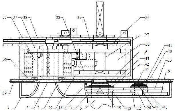
[0033] Combine below Figure 1 to Figure 14 The present invention is further described.

[0034] Such as figure 1 The overall assembly diagram of the lock shown is a technical solution in which the device of the present invention is used in conjunction with an anti-theft lock. The anti-theft lock in this solution is the product corresponding to the eight patents mentioned in the background technology. Wherein, the lock cylinder group 33 and the cam mechanism are all installed between the anti-skid plate 36 and the back plate 37 of the lock body, the transmission mechanism of the lockset is located between the back plate 37 and the buckle cover 38, and the lock bolt and the dead bolt are located at the buckle cover 38. The outside of the door (using an external hanging type movable connection method, not shown in the figure), the entire lock body is installed inside the door leaf, only the key opening 3 is exposed on the door leaf outer panel 39, and the outer end of the camsh...


PUM


Abstract

The invention provides a linkage type handle automatic resetting and idling device and relates to the field of anti-theft locks. The rotation process of a handle is mainly controlled indirectly in a gear transmission manner; the rotating angle of a core component of the device is only half or lower than half the rotating angle of the handle, it is guaranteed that resetting operation can be achieved stably and reliably, and when the handle is rotated within a certain angle in the positive direction and the negative direction, the handle can be reset automatically; when the handle is rotated beyond the certain angle, the handle idles; and when the handle is rotated by a circle, the handle restores the automatic resetting function again. The device is suitable for a lock with a lock body internally provided with an overload protection device, in other words, the handle can be reset automatically, and operation is convenient; and the handle can also idle to prevent the lock from being destroyed or unlocked by a thief.

Description

technical field [0001] The invention relates to the field of anti-theft locks, in particular to a linkage type handle automatic reset and idling device. Background technique [0002] In the prior art, "lock core fixed cross mechanical anti-theft lock" (patent No. ZL201410020215.X), "a double-insert anti-theft door" (patent No. ZL201610068454.1), "double-insert anti-theft door and external lock Closing device" (Patent No. ZL201610129609.8), "A digital code, single key combination kit" (Patent No. ZL201610067763.7), "A profiling device for key matching machine" (Patent No. ZL201610068057.4), "Cylinder fixed cross mechanical anti-theft lock matching with fingerprint lock" (application number 201610990489.0), "a cam mechanism for fingerprint lock" (application number 201611045195.7) and "resetting mechanism for lock cylinder fixed cross mechanical anti-theft lock" ( Application No. 201710193748.1) and other eight invention patent applications, all of which have special structur...

Claims


Application Information

Patent Timeline
Patent Type & Authority Applications(China)
IPC IPC(8): E05B15/00E05B3/08
CPCE05B3/08E05B15/0033E05B15/004
Inventor 吕雪寒张校诚
Owner 重庆山渝道科技有限公司
Why Eureka
Try Eureka