
Lift device assembling method

An assembly method and lift technology, applied to valve devices, engine components, machines/engines, etc., to achieve the effects of reducing fuel consumption, increasing power at medium and high speeds, and increasing torque at low speeds

Inactive Publication Date: 2017-07-14
NANAN FENGZHOU GAOJIE MOTORCYCLE ENERGY SAVING PRACTICAL TECH PROD SALES CENT
View PDF1 Cites 0 Cited by
  • Summary
  • Abstract
  • Description
  • Claims
  • Application Information

AI Technical Summary

Problems solved by technology

[0006] The invention proposes a valve adjustment system and method, which solves the problem of the same valve spring pressure at different engine speeds in the prior art

Method used


Image

  • Lift device assembling method
  • Lift device assembling method
  • Lift device assembling method

Examples


Embodiment Construction

[0052] The following will clearly and completely describe the technical solutions in the embodiments of the present invention with reference to the accompanying drawings in the embodiments of the present invention. Obviously, the described embodiments are only some, not all, embodiments of the present invention. Based on the embodiments of the present invention, all other embodiments obtained by persons of ordinary skill in the art without creative efforts fall within the protection scope of the present invention.

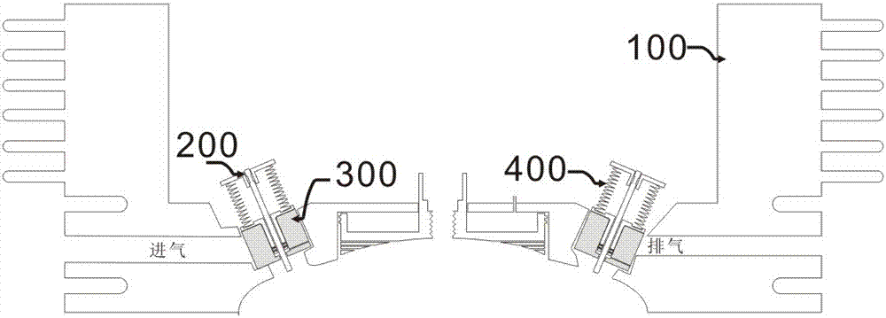
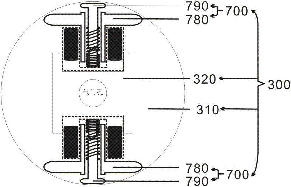
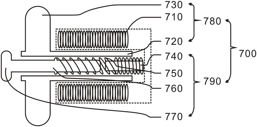
[0053] A method for controlling an engine valve spring, comprising: adjusting pressure to the valve inner spring 400 based on engine speed, adjusting the pressure of the valve inner spring 400 including adjusting an electrical control coupled to a lifter 700 . The valve inner spring 400 is a spring that is sleeved in an outer spring among the two return springs of the valve 200 .

[0054] Among them, such as figure 1 As shown, the valve inner spring 400 is sleeved...


PUM


Abstract

The invention proposes an assembly method of the lift device: first step, the electromagnetic suction and the motor are installed, the runner is installed on the rotor, the shaft center of the rotor is designed as a hollow core, the electromagnetic suction is installed at the bottom of the stator and leads out Two electrical contacts or power lines, the spring is inserted from one end of the push rod to the stepped position of the push rod, the snap piece on the push rod, the push rod is inserted into the rotor and the rotor is inserted into the stator so that the other end of the spring withstands the electromagnetic In the second step, the installed lifters are respectively set on both sides of the balance weight, that is, a lifter is installed on each side of the balance weight; in the third step, the occlusal pieces on both sides are compressed and contracted inward by external force, and then Insert the piston from the runner into rolling combination with the inner wall of the piston; in the fourth step, when the piston descends to the position of the occlusal piece, loosen the occlusal piece to make it integrated.

Description

technical field [0001] The invention relates to a gasoline engine, in particular to an adjustment method capable of changing the valve spring pressure according to the engine speed. Background technique [0002] The valve spring of the engine is the only part that guarantees the valve reset. If the valve spring force is too large, it will seriously damage the wear of the parts of the valve train. If the valve spring force is too small, the valve reset will lag behind, causing the valve and the power piston to collide. [0003] The return force of the valve spring is set according to the maximum speed of the engine to ensure the high-speed operation of the engine. However, the pressure of the valve spring at the highest speed is relatively large, which will inevitably affect the torque of the engine at low speeds. [0004] In order to achieve the reset speed of the valve in some high-speed engines, the valve spring adopts a double spring design, one inner spring and one outer...

Claims


Application Information

Patent Timeline
Patent Type & Authority Applications(China)
IPC IPC(8): F01L13/00F02D13/02
CPCF01L13/00F01L2810/04F02D13/02F02D2200/101
Inventor 庄景阳
Owner NANAN FENGZHOU GAOJIE MOTORCYCLE ENERGY SAVING PRACTICAL TECH PROD SALES CENT
Learn More