Laser visual sensor and detection method thereof
A visual sensor and sensor technology, which is applied in the direction of instruments, measuring devices, and optical devices, can solve the problems of laser energy dispersion, difficulty in application, and weak signal strength, and achieve enhanced irradiation intensity, strong anti-strong light interference, and light intensity bright effect
- Summary
- Abstract
- Description
- Claims
- Application Information
AI Technical Summary
Problems solved by technology
Method used
Image

Examples
Embodiment 1
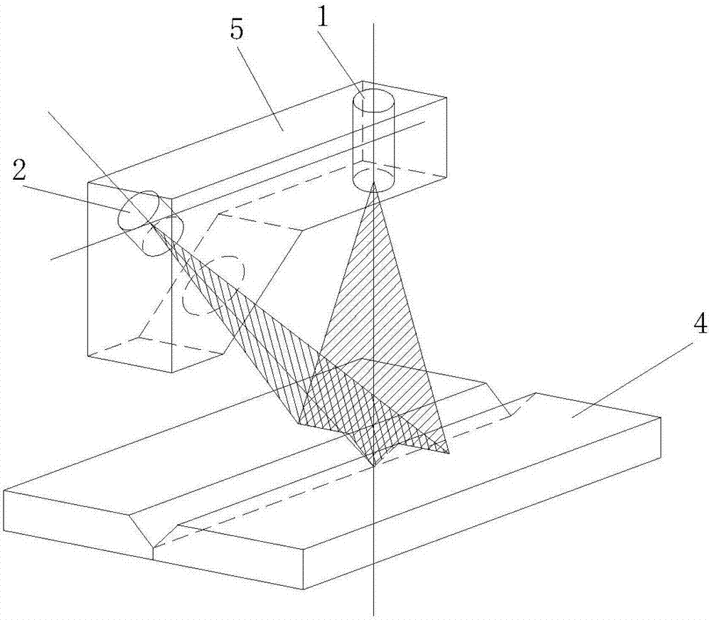
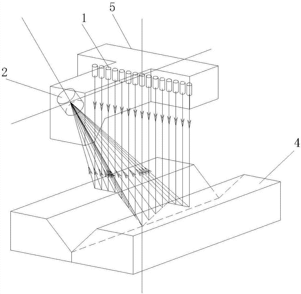
[0035] Such as figure 2 As shown, in the laser vision sensor of this embodiment, the laser transmitter 1 emits a laser beam. If each laser beam is arranged in the same plane, it replaces the laser surface in the conventional laser vision sensor. The only difference is that what is illuminated by the laser is a series of light spots or spots arranged on the cross section, instead of Continuous light pattern of cross-sectional shape. Of course, in theory, the laser beam can be arranged in other ways according to the work task, and it does not have to be in the same plane, but the mathematical model of this arrangement is simple and easy to solve the spot position. These laser transmitters 1 cooperate with the image acquisition sensor 2 to form a laser vision system to obtain the position and depth information of the contour of the workpiece 4 described by points.
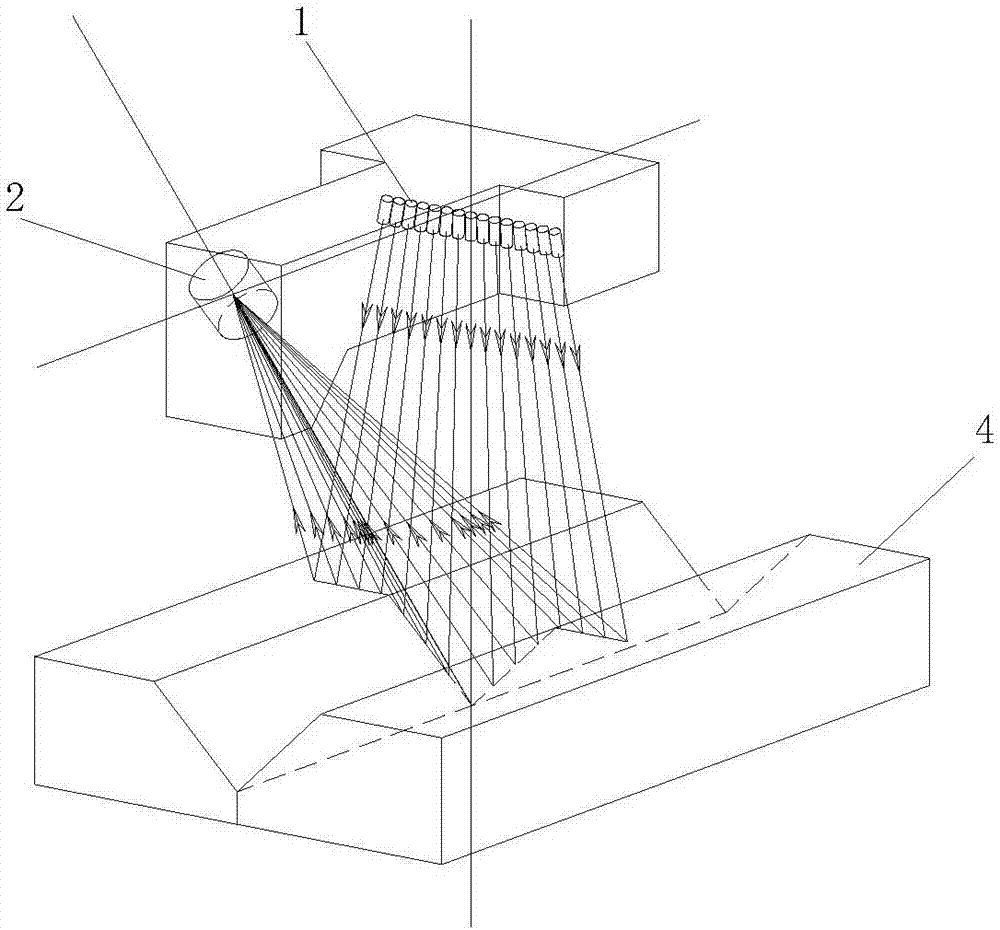
[0036] These laser beams can be arranged in parallel or like image 3 It is arranged in a fan-shaped divergence in o...
Embodiment 2
[0039] In particular, it is also possible to make the main optical axis of the imaging system of the image acquisition sensor coplanar with the plane where the laser beam is located, but the main optical axis of the imaging system and the laser beams are inclined, and the spot generated by the laser beam irradiating the workpiece can be Imaging on the photosensitive surface of the image acquisition sensor, such as Figure 5 Shown. The characteristic of the sensor with this structure is that all the light spots are imaged in a straight line, so the image acquisition sensor can adopt a linear array device (only one line of photosensitive array), and the information processing speed is fast.
[0040] If the actual position and direction of the laser beam have a large error with the design state, the image formed by the light spot will fall outside the photosensitive unit of the linear image acquisition sensor. To this end, an image acquisition sensor with a few rows of photosensitiv...
Embodiment 3
[0043] A reflector 3 can be added in the process of projecting the laser beam to realize folding the optical path and reduce the overall size.
[0044] In particular, using a mirror that can vibrate at a small angle, the deflection angle of the laser beam is also monitored when image information is collected, so that the laser beam can scan between the spots to achieve full coverage of the detection section. Such as Image 6 , Figure 7 As shown, a mirror 3 that vibrates at a slight angle is used. Between the left and right vibration limits, the corresponding spot can scan all the line segments of two adjacent spots, that is, as long as the scanning movement distance of the spot is greater than the adjacent two The maximum distance between the light spots is sufficient. In this way, the number of laser beams can be reduced and a dense detection point spot can also be obtained.
[0045] The above case of using a single vibrating mirror is more suitable for the case where the laser ...
PUM
 Abstract
Description
Claims
Application Information