Fingerprint module manufacturing method and fingerprint module

A technology of fingerprint module and manufacturing method, which is applied in the direction of acquiring/arranging fingerprints/palmprints, character and pattern recognition, instruments, etc., and can solve the problem of fixed and immutable colors of the user interface of fingerprint recognition chips, and achieve the effect of improving the degree of recognition

Inactive Publication Date: 2017-07-14
VIVO MOBILE COMM CO LTD
View PDF2 Cites 0 Cited by
  • Summary
  • Abstract
  • Description
  • Claims
  • Application Information

AI Technical Summary

Problems solved by technology

[0005] The invention provides a fingerprint module manufacturing method and a fingerprint module to solve the problem in the prior art that the color of the user interface of the fingerprint recognition chip is fixed and invariable

Method used


Image

  • Fingerprint module manufacturing method and fingerprint module
  • Fingerprint module manufacturing method and fingerprint module
  • Fingerprint module manufacturing method and fingerprint module

Examples


Embodiment 1

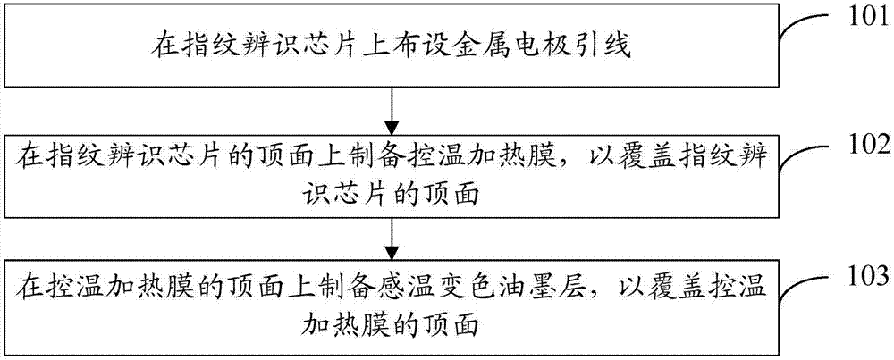
[0020] refer to figure 1 , shows a flow chart of steps of a method for manufacturing a fingerprint module according to Embodiment 1 of the present invention.

[0021] The fingerprint module manufacturing method of the embodiment of the present invention comprises the following steps:

[0022] Step 101: Arranging metal electrode leads on the fingerprint recognition chip.

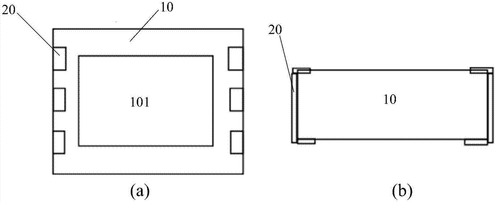
[0023] One end of the metal electrode lead is arranged on the top surface of the fingerprint identification chip, and the other end of the metal electrode lead is connected with the welding pin on the bottom surface of the fingerprint chip. The metal electrode mainly plays the function of electrical signal conduction, and provides heating current for the temperature-controlled heating film.

[0024] Among them, the front schematic diagram of the fingerprint identification chip after the metal electrode leads are laid out is as follows: figure 2 As shown in (a), the side schematic diagram is as follows f...

Embodiment 2

[0039] refer to Figure 6 , shows a flow chart of steps of a method for making a fingerprint module according to Embodiment 2 of the present invention.

[0040] The fingerprint module manufacturing method of the embodiment of the present invention specifically includes the following steps:

[0041] Step 201: Arranging metal electrode leads on the fingerprint recognition chip.

[0042] Wherein, one end of the metal electrode lead is arranged on the top surface of the fingerprint identification chip, and the other end of the metal electrode lead is connected with the welding pin on the bottom surface of the fingerprint chip.

[0043]Specifically, metal electrode leads can be arranged on the fingerprint identification chip by any one of electroplating, metal printing and vacuum sputtering to prepare a thin film.

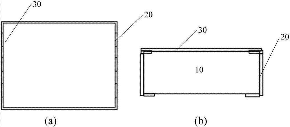
[0044] Step 202: Prepare a temperature-controlled heating film on the top surface of the fingerprint identification chip to cover the top surface of the fingerprint i...


PUM


Abstract

An embodiment of the invention provides a fingerprint module manufacturing method and a fingerprint module. The fingerprint module manufacturing method comprises the steps of: arranging a metal electrode lead wire on a fingerprint identification chip, wherein one end of the metal electrode lead wire is arranged on the top surface of the fingerprint identification chip, and the other end of the metal electrode lead wire is connected with a welding pin on the bottom surface of the fingerprint identification chip; preparing a temperature control heating film on the top surface of the fingerprint identification chip, so as to cover the top surface of the fingerprint identification chip; and preparing a thermochromic ink layer on the top surface of the temperature control heating film, so as to cover the top surface of the temperature control heating film. The fingerprint module prepared by adopting the fingerprint module manufacturing method can exhibit different colors along with different temperatures.

Description

technical field [0001] The invention relates to the technical field of fingerprint module production, in particular to a fingerprint module production method and a fingerprint module. Background technique [0002] Due to the convenience and security of fingerprint recognition, more and more fields of consumer electronics products use fingerprint recognition modules, including mobile phones, cars, bank cards, smart home door locks, etc. Fingerprint recognition modules need to provide an interface for users to enter Fingerprint and identification fingerprint, the fingerprint identification module is usually an appearance part. At present, in order to make the interface provided by the fingerprint module to the user more beautiful, the general method is to spray a certain color ink on the fingerprint recognition chip, or cover a certain color ink and a cover plate on the fingerprint recognition chip, so as to provide consumers with a pleasant experience. user interface. [00...

Claims


Application Information

Patent Timeline
Patent Type & Authority Applications(China)
IPC IPC(8): G06K9/00
CPCG06V40/12G06V10/94
Inventor 杨俊
Owner VIVO MOBILE COMM CO LTD
Why Eureka
Try Eureka