Check patentability & draft patents in minutes with Patsnap Eureka AI!

Chip batch positioning system

A positioning system and chip technology, applied in electrical components, semiconductor/solid-state device manufacturing, circuits, etc., can solve the problems of low chip efficiency and difficulty in mass production, and achieve the effect of improving work efficiency, ensuring accurate positioning, and facilitating shaking

Pending Publication Date: 2017-07-14
RUGAO DACHANG ELECTRONICS
View PDF5 Cites 0 Cited by
  • Summary
  • Abstract
  • Description
  • Claims
  • Application Information

AI Technical Summary

Problems solved by technology

[0003] The technical problem to be solved by the present invention is that the existing manual placement of chips is inefficient and difficult to meet the needs of mass production

Method used


Image

  • Chip batch positioning system
  • Chip batch positioning system
  • Chip batch positioning system

Examples


Embodiment Construction

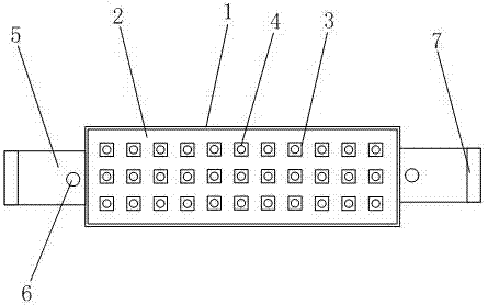
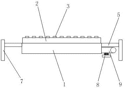
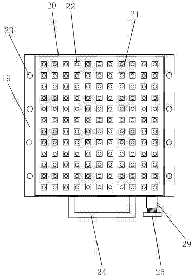
[0020] Such as Figure 1-6 As shown, a chip batch positioning system disclosed in the present invention includes: a suction board device, a suction pen device and an air source system.

[0021] Wherein, the suction plate device comprises a suction plate base 19, a rectangular frame 20 and a base air valve; the rectangular frame 20 is installed on the top of the suction plate base 19; 28; chip slots 21 are arranged in an array on the upper part of the suction plate base 19 and in the rectangular frame 20; chip air holes 22 are provided at the bottom of the chip slot 21; The base air cavity of the base; the left and right side edges of the suction plate base 19 tops are provided with positioning columns 23; the base air valve is installed on the side of the suction plate base 19 and communicates with the base air cavity; the pen suction device includes a strip plate 1 and Suction pen air valve; a boss 2 is provided on the upper part of the strip plate 1; a positioning bump 3 co...


PUM


Abstract

The invention provides a chip batch positioning system, which comprises a plate sucking device, a pen sucking device and an air source system, and is characterized in that the plate sucking device comprises a plate sucking base, a rectangular frame and a base air valve; the rectangular frame is installed at the upper part of the plate sucking base; the lower part of the plate sucking plate is provided with supporting columns, and the lower end of each supporting column is provided with a ball; the upper part of the plate sucking base is provided with chip grooves; the bottom of each chip groove is provided with a chip air hole; the plate sucking base is internally provided with a base air cavity; the base air valve is communicated with the base air cavity; the pen sucking device comprises a strip-shaped plate and a pen sucking air valve; the upper part of the strip-shaped plate is provided with a boss; the boss is provided with positioning convex blocks, and each positioning convex block is provided with a pen sucking air hole; and the strip-shaped plate is internally provided with a pen sucking air cavity; and the pen sucking air valve is communicated with the pen sucking air cavity. The chip batch positioning system can realize positioning and transferring of chips in batches, and effectively improves the work efficiency. In addition, the whole positioning and transferring operation can be completed by one operator, so that the chip batch positioning systems saves time and labor.

Description

technical field [0001] The invention relates to a chip positioning system, in particular to a chip batch positioning system. Background technique [0002] At present, in the process of manufacturing microchips, it is necessary to position each small chip in batches, so as to facilitate the batch welding of chips; but the existing positioning relies on manual placement one by one, which leads to low work efficiency and is difficult to meet the needs of mass production. . Contents of the invention [0003] The technical problem to be solved by the invention is that the existing manual placement of chips is inefficient and difficult to meet the needs of mass production. [0004] In order to solve the above technical problems, the present invention provides a batch positioning system for chips, which includes a suction board device, a suction pen device and an air source system; the suction board device includes a suction board base, a rectangular frame and a base air valve; ...

Claims


Application Information

Patent Timeline
IPC IPC(8): H01L21/68H01L21/683
CPCH01L21/68H01L21/6838
Inventor 王志敏黄丽凤
Owner RUGAO DACHANG ELECTRONICS
Features
  • R&D
  • Intellectual Property
  • Life Sciences
  • Materials
  • Tech Scout
  • Unparalleled Data Quality
  • Higher Quality Content
  • 60% Fewer Hallucinations
Learn More