
Device for adjusting container position and robot

An adjustment device and robot technology, applied in the field of robots, can solve the problems of single adjustment method, poor suction effect, and low space utilization rate of dispensing robots

Pending Publication Date: 2017-07-18
SHENZHEN CITY WEIBANG TECH
View PDF6 Cites 2 Cited by
  • Summary
  • Abstract
  • Description
  • Claims
  • Application Information

AI Technical Summary

Problems solved by technology

[0006] The present invention aims to solve the problems that the traditional container position adjustment method is single, the space utilization rate of the dispensing robot is too low, and it is easy to get stuck with the needle, and the suction effect is poor. It provides a container position adjustment device and robot, technical solution as follows:

Method used


Image

  • Device for adjusting container position and robot

Examples


Embodiment 1

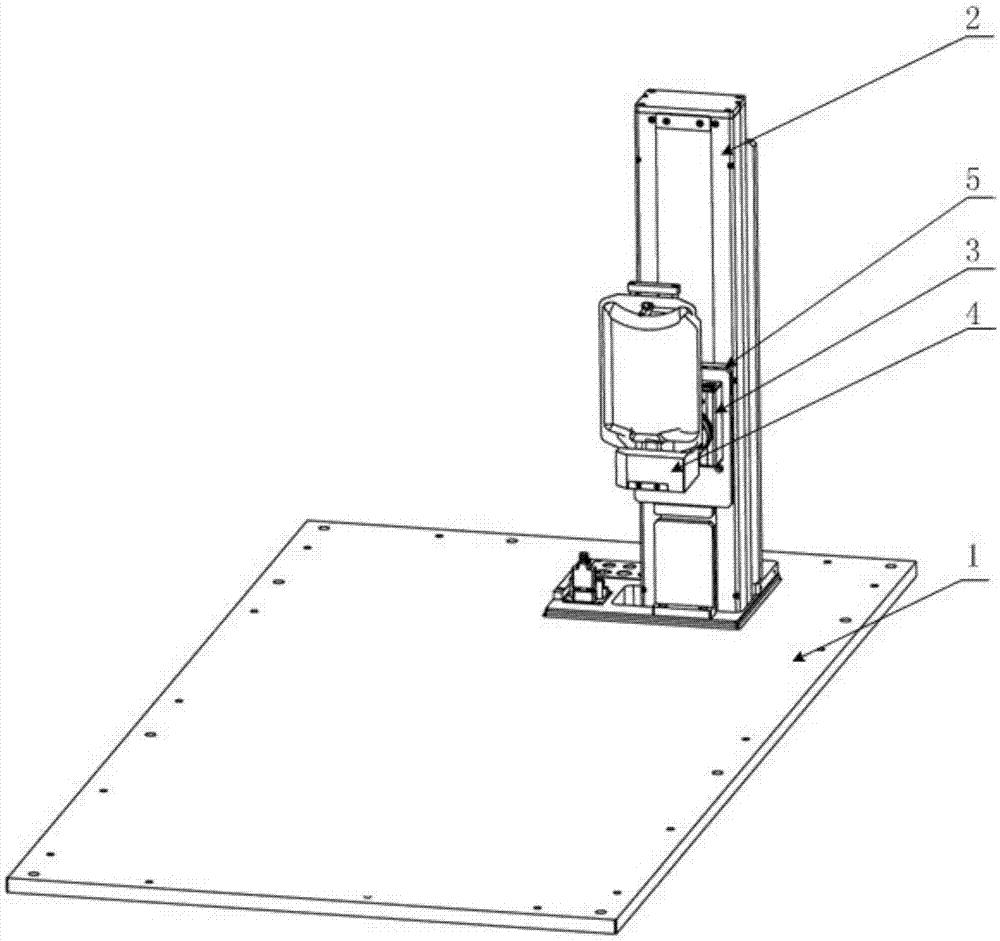
[0028] Such as figure 1 As shown, a container position adjustment device provided by the present invention includes a base plate 1 , a slide table 2 , a rotary table 3 and a container clamp 4 .

[0029] The slide table 2 is connected with the base plate 1 , the rotary table 3 is connected with the slide table 2 through the slide seat 5 , and the container fixture 4 is connected with the rotary table 3 . In this embodiment, the sliding seat 5 can drive the rotating table 3 to move on the sliding table 2 , and the rotating table 3 drives the container fixture 4 to rotate around the axis of the rotating table 3 .

[0030] The container clamp 4 is used to hold the container. Preferably, the container clamp 4 can include a soft bag clamp, a plastic bottle clamp and a glass bottle clamp, which can be used to clamp soft bags, plastic bottles, glass bottles and the like respectively. Those skilled in the art should understand that the container types listed in this embodiment are on...

Embodiment 2

[0036] The present invention provides a robot, including a robot body and the container position adjustment device provided in Embodiment 1 of the present invention. For the specific structure of the container position adjustment device, please refer to the description in Embodiment 1, which will not be repeated here.

[0037] When the robot provided by the present invention is used in an automatic dispensing system, a plurality of functional modules are installed on the same substrate, which has a compact structure and high space utilization; through the vertical movement of the container in the container position adjustment device, the needle of the dispensing device is inserted into the After the container is installed, there is no need to adjust the posture of the container to obtain a better absorption effect, and there will be no pins due to posture problems. When there is less solution in the container, the input solution will not cause needles to be sucked into the conta...


PUM


Abstract

The invention relates to the field of a robot and specifically discloses a device for adjusting a container position and the robot. The device for adjusting the container position provided by the invention comprises a base plate, a sliding table, a rotating table and a container clamp, wherein the sliding table is connected with the base plate; the rotating table is connected with the sliding table through a sliding base; the rotating table is driven by the sliding base to move on the sliding table; the container clamp is connected with the rotating table; the container clamp is driven by the rotating table to rotate by taking the axis of the rotating table as the center; and the container clamp is used for clamping the container. When the device for adjusting the container position provided by the invention is applied to an automatic dosing system based on the robot, a needle instrument of a dosing device is inserted into the container through the vertical motion of the container, and then the container posture does not need to be adjusted for acquiring the optimal absorbing effect and the needle shifting caused by the gesture problem can be avoided, and when less solution is in the container, the phenomenon of the needle instrument sucking air in the container caused by the gesture problem also can be avoided in the process of inputting the solution.

Description

[0001] 【Technical field】 [0002] The invention relates to the field of robots, in particular to a container position adjustment device and a robot. [0003] 【Background technique】 [0004] During the dispensing process of the dispensing robot, some drugs need to be diluted with a solvent, so the solvent will be drawn out or pumped into the solvent container. During this process, the solvent container needs to move or adjust its posture to adapt to multiple pumping processes. The traditional method They all use horizontal movement and small posture adjustment to adjust the posture of the solvent container, but the horizontal movement of the solvent container takes up a lot of space, the space utilization rate of the dispensing robot is low, and it is not compact enough, and the solvent container is placed horizontally. The small adjustment process of its posture is easy to get stuck with the needle, and the effect of suction is poor. [0005] 【Content of invention】 [0006] T...

Claims


Application Information

Patent Timeline
IPC IPC(8): B01F15/00
CPCB01F35/423
Inventor 刘葆春吴建文黄伟
Owner SHENZHEN CITY WEIBANG TECH
Learn More