
Milling cutter clamping device convenient to install

A milling cutter holder and milling cutter technology, which is applied to milling machine equipment, milling machine equipment details, metal processing equipment, etc., can solve the problems of milling cutter deflection and falling off, inconvenient replacement, and small holding force, so as to achieve simple structure and improve work efficiency. Efficiency, enhance the effect of blessing

Inactive Publication Date: 2017-07-18
CHENGDU HENGTONG ZHAOYE PRECISION MACHINERY
View PDF12 Cites 7 Cited by
  • Summary
  • Abstract
  • Description
  • Claims
  • Application Information

AI Technical Summary

Problems solved by technology

[0003] The technical problem to be solved by the present invention is that the existing milling cutter clamping device has small clamping force and low precision, and the milling cutter is prone to deflection and falling off, and it is inconvenient to replace. The purpose is to provide an easy-to-install milling cutter clamping device that can Increase the holding force of the milling cutter, prevent the tool from deflecting or falling off, improve stability and safety, and at the same time realize rapid tool replacement and improve work efficiency

Method used


Image

  • Milling cutter clamping device convenient to install

Examples


Embodiment

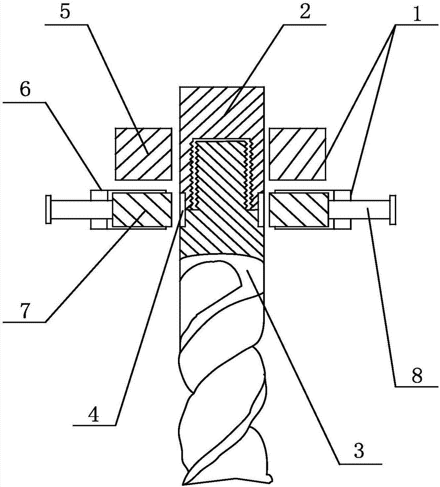
[0021] Such as figure 1 As shown, the present invention is an easy-to-install milling cutter clamping device, comprising a clamping seat 1, a milling cutter shank 2 fixed on the clamping seat, a milling cutter head 3 connected to the lower end of the milling cutter shank, and a milling cutter The knife handle and the milling cutter head are connected by threads, and the connection between the milling cutter handle and the milling cutter head is provided with a plurality of limit grooves 4; the clamping seat includes a knife handle clamping seat 5 and a limit Position clamping seat 6, the knife handle clamping seat is used for clamping the milling cutter shank, and the described limit clamping seat is positioned at the outside of the junction of the milling cutter handle and the milling cutter head, and the limit clamping seat is provided with Limit block 7, the shape of the limit block matches the shape of the limit groove, and the limit block moves back and forth along the di...


PUM


Abstract

The invention discloses an easy-to-install milling cutter clamping device, which comprises a clamping seat, a milling cutter handle fixed on the clamping seat, the lower end of the milling cutter handle is connected with a milling cutter head, and the milling cutter handle is connected with the milling cutter holder. The milling cutter heads are connected by threads, and the connection between the milling cutter handle and the milling cutter head is provided with a plurality of limit grooves; the clamping seat includes a tool handle clamping seat and a limit clamping seat, and the cutter The shank clamping seat is used for clamping the milling cutter shank, and the limit clamping seat is located on the outside of the connection between the milling cutter shank and the milling cutter head, and the limit clamping seat is provided with a limit block, and the limit block The shape matches the shape of the limit groove, and the limit block moves back and forth along the direction of the limit groove. The milling cutter clamping device of the present invention can increase the clamping force on the milling cutter, prevent the cutter from deflecting or falling off, improve stability and safety, and at the same time realize rapid replacement of the cutter and improve work efficiency.

Description

technical field [0001] The invention relates to the technical field of precision machinery manufacturing equipment, in particular to an easy-to-install milling cutter clamping device. Background technique [0002] A milling cutter is a rotating tool with one or more teeth for milling. When working, each knife tooth cuts off the allowance of the workpiece intermittently in turn. Milling cutters are mainly used for machining planes, steps, grooves, forming surfaces and cutting off workpieces on milling machines. It plays an important role in the processing of mechanical equipment. In addition to selecting high-performance cutting tools during processing, the requirements for the clamping equipment of milling cutters are also getting higher and higher. For the clamping equipment used in precision machinery manufacturing, it must not only have good clamping rotation accuracy, but also should It has excellent dynamic balance performance and dynamic performance, and the commonl...

Claims


Application Information

Patent Timeline
IPC IPC(8): B23C9/00
CPCB23C9/005
Inventor 吴光武
Owner CHENGDU HENGTONG ZHAOYE PRECISION MACHINERY
Learn More