
Welding method of hydraulic bracket shield beam

A technology of hydraulic supports and shielding beams, which is applied in welding equipment, welding equipment, auxiliary welding equipment, etc., and can solve the problems that are difficult to meet the production requirements of tailor welding robots, the weld seams of four sets of main rib components are difficult to weld, internal rib plates, and cover plates Difficulties and other problems, to achieve the effect of reducing the difficulty of tailor welding, improving the efficiency of tailor welding, and reducing the amount of welding deformation

Active Publication Date: 2017-07-18
ZHENGZHOU COAL MINING MACHINERY GRP
View PDF6 Cites 18 Cited by
  • Summary
  • Abstract
  • Description
  • Claims
  • Application Information

AI Technical Summary

Problems solved by technology

[0003] With the advancement of technology, the automatic operation method of welding robot is gradually being applied to the tailor welding of hydraulic support structural parts, while the traditional tailor welding method is obviously difficult to meet the production requirements of tailor welding robot
Especially in the way of directly assembling the four sets of main rib components on the top plate, due to the limitation of the robot welding torch, most of the welds on the four sets of main rib components after assembly will be difficult to weld, and if the four sets of main rib components are assembled before assembly The welds are all welded well, and a large amount of welding will lead to serious deformation of the main ribs, which will cause great difficulties in the subsequent assembly of internal ribs, cover plates and other components

Method used


Image

  • Welding method of hydraulic bracket shield beam
  • Welding method of hydraulic bracket shield beam
  • Welding method of hydraulic bracket shield beam

Examples


Embodiment Construction

[0026] The embodiments of the present invention will be described in detail below in conjunction with the accompanying drawings. This embodiment is implemented on the premise of the technical solution of the present invention, and detailed implementation methods and specific operating procedures are provided, but the scope of protection of the present invention is not limited to the following Described embodiment.

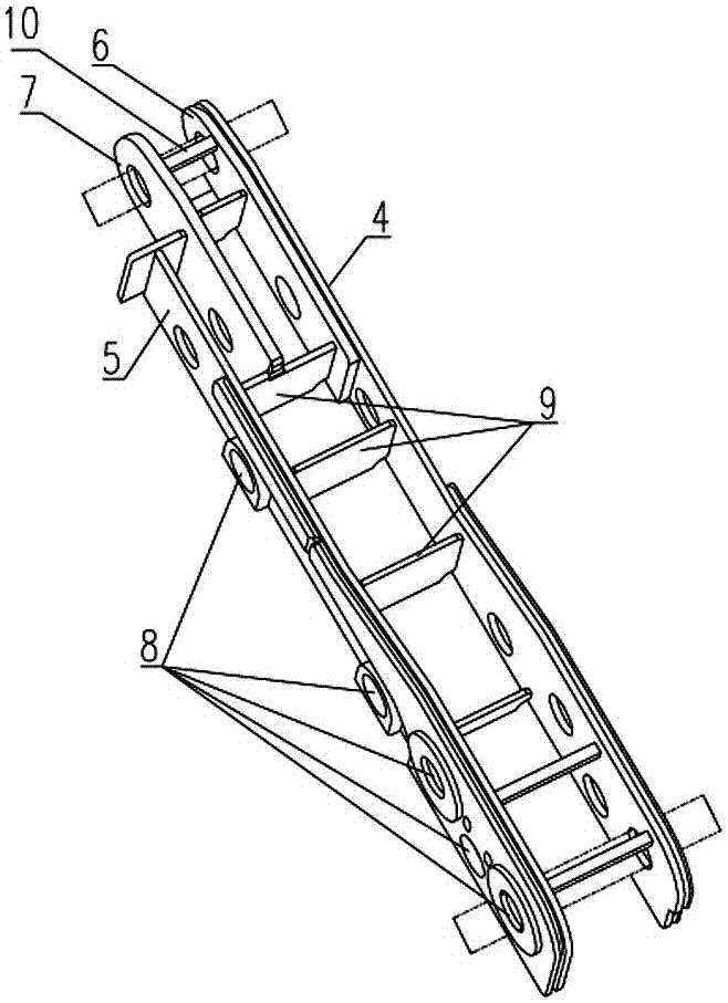
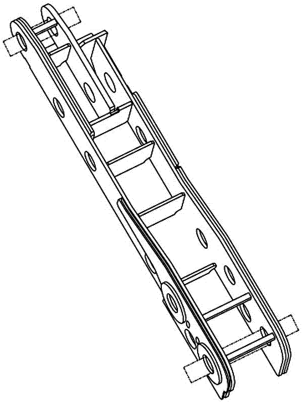
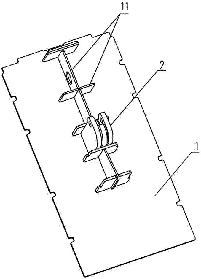
[0027] Such as Figure 1-5 As shown, the tailor welding method of the hydraulic support shield beam of the present invention includes the tailor welding of the left box-shaped main reinforcement, the right box-shaped main reinforcement, the top plate 1, the balance ear seat 2 and the cover plate 3; carry out according to the following steps:

[0028] The first step, the tailor welding of the left box-shaped main reinforcement and the right box-shaped main reinforcement:

[0029] a. Place the inner main ribs 4, the outer main ribs 5, the inner hinged lugs 6, and th...


PUM


Abstract

The invention discloses a welding method of a hydraulic bracket shield beam. The welding method comprises welding of a left box-shaped main rib, a right box-shaped main rib, a top plate, a balance lug base and a cover plate: (1) welding of the left box-shaped main rib and the right box-shaped main rib: inner main rib plates, outer main rib plates, inner hinge lug plates and outer hinge lug plates of the left and right box-shaped main ribs are put in appointed positions of an assembly platform; and internal rib plates are assembled between the inner and outer main rib plates of the left and right box-shaped main ribs for positioned welding for reinforcement; (2) welding of the top plate and the balance lug the top plate is put in an appointed position of the assembly platform; and a middle rib plate module and the balance lug base are assembled in the middle position of the surface of the top plate for positioned welding and reinforcement; (3) the left box-shaped main rib and the right box-shaped main rib are assembled together; and (4) the shield beam is overally welded. The welding method of the hydraulic bracket shield beam has the advantages of simple welding process, high operability, large reduction of the welding difficulty under the precondition of guaranteeing the assembly precision, and improvement of the welding efficiency.

Description

technical field [0001] The invention relates to a hydraulic support shield beam, in particular to a tailor welding method for a hydraulic support shield beam. Background technique [0002] As the main support equipment in coal mine fully mechanized mining equipment, hydraulic support has the characteristics of large volume and weight, harsh service conditions, and many box-type welded structures. The cover beam is the main structural part of the hydraulic support, which is composed of box-shaped main rib components, top plate, internal rib plate, ear plate, cover plate and other parts. At present, the tailor welding method in the manufacturing process of the cover beam is to first draw the position lines of the four main ribs on the top plate, and then use the mandrel to assemble four sets of main rib components (for welds that are difficult to weld after assembly, pre-buried Welding), then use the inspection mandrel to inspect the coaxiality of the hinge holes of the four ...

Claims


Application Information

Patent Timeline
IPC IPC(8): B23K31/00B23K37/00B23K101/28
CPCB23K31/003B23K37/00B23K2101/28
Inventor 高有进孟贺超付金良赵旭程相榜兰志宇孟凡炯段青辰赵建庄
Owner ZHENGZHOU COAL MINING MACHINERY GRP
Learn More