Intelligent automatic cutting device

An automatic cutting, one-pair technology, applied in metal processing and other directions, can solve problems such as low cutting efficiency, and achieve the effect of simple and reasonable settings

Inactive Publication Date: 2017-07-18
镇江倍斯特曼新材料研究有限公司
View PDF6 Cites 7 Cited by
  • Summary
  • Abstract
  • Description
  • Claims
  • Application Information

AI Technical Summary

Problems solved by technology

[0002] At present, most of the pipe cutting process is carried out by semi-manual methods, resulting in low cutting efficiency

Method used


Image

  • Intelligent automatic cutting device
  • Intelligent automatic cutting device

Examples


Embodiment Construction

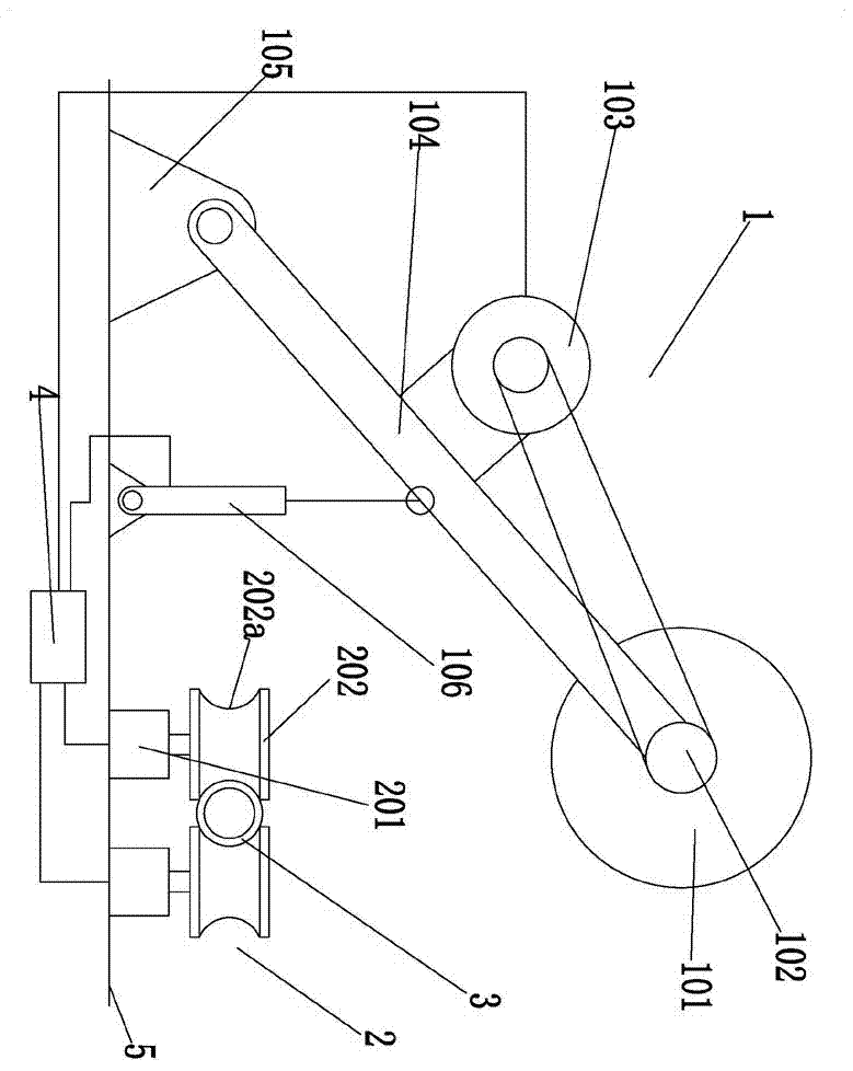
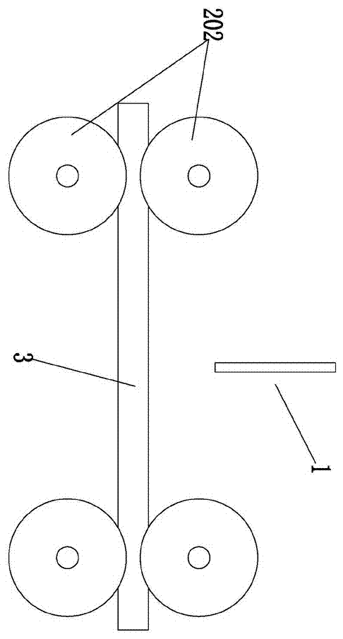
[0012] Such as Figure 1-2 As shown, an intelligent automatic cutting device includes a cutting assembly 1, a feeding assembly 2, and an electric control center 4.

[0013] The above-mentioned feeding assembly 2 is provided with two pairs, and the two pairs of feeding assemblies 2 are arranged at intervals, and each pair of feeding assemblies 2 is arranged side by side. The feeding assembly 2 includes a bottom drive motor 201 and a feed wheel 202. The bottom drive motor 201 is fixed on the ground foundation 5 The feeding wheel 202 can perform horizontal rotation under the control of the bottom drive motor 201. The feeding wheel 202 is a rotary structure and its central axis is the center of rotation. The outer periphery of the feeding wheel 202 is provided with an arc groove 202a. When feeding, each pair of feeding components The arc-shaped grooves 202a of 2 all clamp and hug the outer periphery of the pipe material 3.

[0014] The above-mentioned cutting assembly 1 includes ...


PUM


Abstract

The invention discloses an intelligent automatic cutting device in the technical field of automatic manufacturing, which includes a material cutting assembly, a feeding assembly, and an electric control center; two pairs of feeding assemblies are provided, and the two pairs of feeding assemblies are arranged at intervals, and each pair of feeding assemblies is arranged side by side Setting, the feeding assembly includes a bottom drive motor and a feeding wheel; the cutting assembly includes a cutter head, a rotating shaft, a cutting motor, a movable connecting rod, a bottom hinge seat, and an electric push rod; the bottom driving motor, a cutting motor, and an electric push rod The rods are all controlled by the electric control center. Pipes can be cut off efficiently and automatically.

Description

technical field [0001] The invention relates to the technical field of automatic manufacturing, in particular to a device for automatically cutting pipes. Background technique [0002] At present, most of the pipe cutting process is carried out in a semi-manual way, resulting in low cutting efficiency. Contents of the invention [0003] The purpose of the present invention is to provide an intelligent automatic cutting device, which can efficiently and automatically cut pipes. [0004] The object of the present invention is achieved in this way: an intelligent automatic cutting device, including a material cutting assembly, a feeding assembly, and an electric control center; [0005] The feeding assembly is provided with two pairs, and the two pairs of feeding assemblies are arranged at intervals, and each pair of feeding assemblies is arranged side by side. The feeding assembly includes a bottom driving motor and a feeding wheel, and the bottom driving motor is fixed on ...

Claims


Application Information

Patent Timeline
IPC IPC(8): B26D1/16B26D5/06B26D5/08B26D7/06
CPCB26D1/16B26D5/06B26D5/086B26D7/06
Inventor 袁潘臣
Owner 镇江倍斯特曼新材料研究有限公司
Why Eureka
Try Eureka