Electromechanical tracking power supply device

A technology of power supply device and mobile power supply, which is applied in circuit devices, electric vehicles, current collectors, etc., can solve the problems of difficulty in realizing electric machinery, shortening the surface of power supply and receiving surface, and increasing cost.

Pending Publication Date: 2017-07-18
杭州蓝力电动科技有限公司
View PDF6 Cites 1 Cited by
  • Summary
  • Abstract
  • Description
  • Claims
  • Application Information

AI Technical Summary

Problems solved by technology

Objectively, the cost is greatly increased, and the application range of these machines is also limited.
[0003] Although non-wired power transmission technologies such as electromagnetic induction or high-energy microwave are constantly improving, in order for these power transmission methods to be transmitted efficiently, it is necessary to increase the transmission area as much as possible and shorten the power supply panel and power receiving area. The distance between the disks is difficult to achieve for driving or working electric machinery

Method used


Image

  • Electromechanical tracking power supply device
  • Electromechanical tracking power supply device

Examples


Embodiment 1

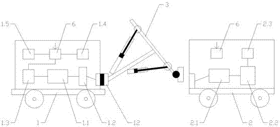
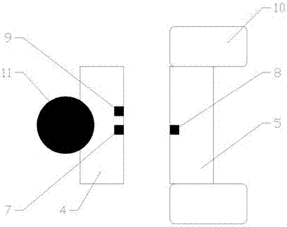
[0027] Example 1: Combining figure 2 As shown, the power supply joint is a power supply plate 4 capable of emitting electromagnetic waves, the power supply plate 4 is equipped with a force sensor 9 , the power receiving joint is a power receiving plate 5 capable of receiving electromagnetic waves, and the power receiving plate 5 is surrounded by insulating materials 10 . After the power supply plate 4 and the power receiving plate 5 are in contact, the contact state of the two is sensed by the force sensor 9. When the electric machine 2 is moving, the manipulator control device 1.4 on the movable power supply vehicle 1 controls the manipulator 3 to move accordingly and keep in contact. The force is within a certain range, so that the power supply board 4 and the power receiving board 5 are always tightly connected.

[0028] In addition, the power supply plate 4 is connected to the manipulator 3 through the ball joint 11, and the manipulator 3 is connected to the movable power...

Embodiment 2

[0029] Embodiment 2: The difference with Embodiment 1 is that the power receiving plate 5 is provided with a holding device capable of fixing the power supply plate 4, such as a magnetic device. After the manipulator 3 places the power supply plate 4 on the power receiving plate 5, the receiving plate The electric plate 5 emits an electromagnetic suction force to attract the power supply plate 4 on the electric receiving plate 5, and the manipulator control device 1.4 relaxes the driving force of each joint on the manipulator 3, and the manipulator 3 can freely stretch and contract along with the movement of the electric machine 2, so that There is no need to continuously control the manipulator 3 during the power supply process to maintain the pressure of the power supply plate 4 on the power receiving plate 5, and when the electric machine 2 suddenly accelerates or decelerates, each joint will be in a braking state, thereby slowing down the speed change.


PUM


Abstract

An electromechanical tracking power supply device comprises a mobile power supply vehicle and an electric machinery; a power supply and an output power conversion device are arranged in the mobile power supply vehicle; an input power conversion device, a battery and a motor are arranged in the electric machinery; a telescopic manipulator is arranged at the front part of the mobile power supply vehicle; a power supply connector is arranged at the front end of the telescopic manipulator; a power receiving connector is arranged at the tail part of the electric machinery; and the telescopic manipulator is operated to connect the power supply connector with the power receiving connector so that electric energy in the mobile power supply vehicle can be transmitted to the electric machinery. The invention provides a novel scheme which can give full play to an unconnected type power transmission technology and can solve problems of lack of power in road machinery and non-road machinery during moving; and by controlling the manipulator, the electromechanical tracking power supply device can also keep stable power transmission in an electromechanical moving state.

Description

technical field [0001] The invention belongs to the technical field of engineering machinery and equipment, and relates to power transmission technology, engineering machinery technology, communication technology, and control technology. Specifically, it is a tracking power supply device for electric machinery. Background technique [0002] Electric road machines or non-road machines are running or working, if the power of the battery is insufficient, they have to stop working and replace the battery or charge it. But there are many situations where it is not allowed to stop work halfway. For example, if an electric car is walking on a highway, it is impossible to allow it to stop on the side of the road because it is out of power. When an excavator is working on a steep slope, it is impossible to walk down for charging. Charge. Therefore, for such a machine, in order to avoid the state of insufficient power halfway, it is necessary to reserve a large battery reserve. Obje...

Claims


Application Information

Patent Timeline
Patent Type & Authority Applications(China)
IPC IPC(8): B60L9/00B60L5/00H02J50/00H02J50/90
CPCB60L5/00B60L9/00
Inventor 刘昱可坚祝韩星
Owner 杭州蓝力电动科技有限公司
Why Eureka
Try Eureka