Platform door structure, platform guardrail manufacturing method and setting method

A manufacturing method and platform door technology, which is applied to building structures, stations, door/window accessories, etc., can solve problems such as the cost impact of platform guardrails, and achieve the effect of setting costs

Inactive Publication Date: 2017-07-18
NABLESCO CORP
View PDF5 Cites 0 Cited by
  • Summary
  • Abstract
  • Description
  • Claims
  • Application Information

AI Technical Summary

Problems solved by technology

This has a great impact on the instal

Method used


Image

  • Platform door structure, platform guardrail manufacturing method and setting method
  • Platform door structure, platform guardrail manufacturing method and setting method
  • Platform door structure, platform guardrail manufacturing method and setting method

Examples


no. 1 approach

[0025] It usually takes several weeks to complete the platform railing on the platform. Thus, causing passengers to enter the train through unfinished platform guardrails. Or, cause passengers to disembark from the train through an unfinished platform barrier. In the following description, the term "platform door structure" refers to an unfinished platform guardrail (a state in which some door units have not yet been installed). In the first embodiment, an exemplary platform door structure capable of performing safety confirmation on the condition that the door space is in a closed state will be described.

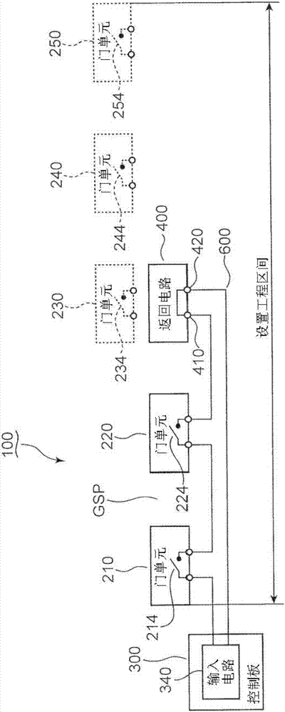
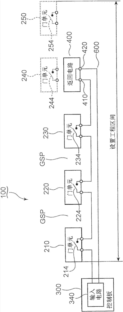
[0026] figure 1 It is a schematic diagram of the platform door structure 100 of 1st Embodiment. refer to figure 1 The platform door structure 100 will be described.

[0027] figure 1 Door units 210 , 220 , 230 , 240 , 250 are shown schematically. The platform guardrail is completed by arranging the door units 210, 220, 230, 240, 250 on the platform (not shown). fig...

no. 2 approach

[0079] With the technology described in connection with the first embodiment, the operator can arrange the return circuit near the door unit installed on the platform. However, according to the technique of the first embodiment, a worker needs to move the return circuit every time a door unit is added. In 2nd Embodiment, the technique which can add a gate unit to a closed loop circuit without an operator moving a return circuit is demonstrated.

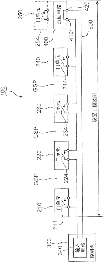
[0080] Figure 6 It is a schematic diagram of 100 A of platform door structures of 2nd Embodiment. refer to figure 2 , Figure 4 to Figure 6 The platform door structure 100A will be described. The same reference numerals are assigned to the same elements as in the first embodiment. The description of the first embodiment is referred to the components denoted by the same reference numerals.

[0081] Similar to the first embodiment, 100A of platform door structures include door units 210 and 220 and a control panel 300 . The des...

no. 3 approach

[0088] The return circuit described in connection with the first embodiment and the second embodiment may only have a function of directly outputting an input signal. Thus, the return circuit can have a very simple circuit configuration. In the third embodiment, an exemplary circuit configuration of a return circuit will be described.

[0089] Figure 9 It is a schematic plan view of the return circuit 430 of the third embodiment. refer to figure 1 , Figure 6 as well as Figure 9 The return circuit 430 will now be described.

[0090]return circuit 430 can serve as a reference figure 1 The illustrated return circuit 400 or refer to Figure 6 The illustrated return circuit 400A is used. The return circuit 430 includes a substrate 431 and a printed layer 432 . The printing layer 432 is formed on the substrate 431 .

[0091] The printing layer 432 includes a first contact portion 433 , a second contact portion 434 and a connection line portion 435 . The first contact p...


PUM


Abstract

Platform door structure, platform guardrail manufacturing method and setting method are provided; the station door structure includes: a first door unit which is provided on a platform as a door unit in a plurality of door units; a confirmation signal generating unit that outputs an acknowledgment signal for confirming the opening / closing state of the door space formed by the first door unit to the first door unit; and a return circuit that cooperates with the first gate unit and the confirmation signal generation unit to form a closed loop circuit that determines a transmission path of a signal for confirming the signal generation unit as a starting point and an end point. If the state is normal, the first gate unit closes the closed loop circuit to allow confirmation of the transmission of the signal to the return circuit. The return circuit returns the confirmation signal received from the first gate unit to the confirmation signal generation unit.

Description

technical field [0001] The present invention relates to a technique for arranging a platform guardrail on a platform. Background technique [0002] Platform guardrails are used in various stations. The platform guardrail isolates the passengers on the platform from the track space on which the train passes. As a result, passengers can be appropriately protected by the platform guardrail (see JP-A-2011-20657). When the train stops, the platform guardrail forms a door space in front of the entrance and exit of the train. As a result, passengers can come and go between the platform and the train through the gate and door space of the train. [0003] It usually takes several weeks to complete the platform railing on the platform. Thus, passengers are caused to use platforms provided with unfinished platform guardrails. [0004] The platform guardrail consists of multiple door units arranged on the platform. The above-mentioned door spaces are formed between adjacent door u...

Claims


Application Information

Patent Timeline
IPC IPC(8): B61B1/02
CPCB61B1/02E01F1/00E05Y2900/404E05F15/40
Inventor 福田伸行
Owner NABLESCO CORP
Why Eureka
Try Eureka