Power cabinet for sample pneumatic conveying system

A technology of pneumatic conveying and power cabinets, applied in the field of power cabinets, can solve the problems of large energy consumption loss, complicated pipeline connection, large fan vibration, etc., and achieve the effect of ensuring physical characteristics and precision, simple pipeline connection, and simple and compact structure

Pending Publication Date: 2017-07-18
HUNAN SUNDY SCI & TECH DEV
View PDF8 Cites 1 Cited by
  • Summary
  • Abstract
  • Description
  • Claims
  • Application Information

AI Technical Summary

Problems solved by technology

[0005] (1) The existing power cabinet uses two fans for blowing and exhausting operations. The installation of the two fans leads to a larger overall equipment and requires a larger space for placement, resulting in high requirements for the use of the site
[0006] (2) The setting of double fans makes the cost high, the pipeline connection inside the cabinet is complicated, and it is inconvenient to repair and maintain
[0007] (3) The setting of double fans causes large vibration of the fans, which damages the airtightness of the pneumatic transmission pipeline. At the same time, due to the high noise of the double fans, it is not environmentally friendly
This leads to high cost and large equipment
Second, whether it is the design of two cabinets or the design of two fans in one cabinet, in the production operation, the two fans may conflict, that is, the other one is also drawing air at the same time when it is time to blow, which seriously affects the safety of pneumatic transmission. May cause breakage of tubing and vials, seriously affecting sample physical properties and precision
In particular, the status of the two fans cannot be flexibly adjusted according to the real-time pressure conditions in the airway transmission pipeline, which makes the risk greater
Big energy loss

Method used


Image

  • Power cabinet for sample pneumatic conveying system
  • Power cabinet for sample pneumatic conveying system
  • Power cabinet for sample pneumatic conveying system

Examples


Embodiment Construction

[0029] The present invention will be described in further detail below in conjunction with specific embodiments and accompanying drawings.

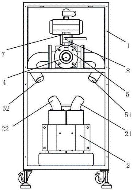
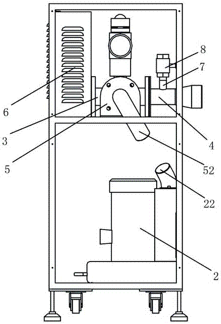
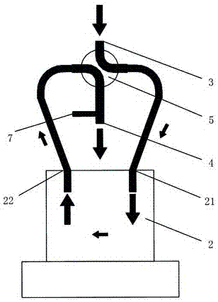
[0030] Such as Figure 1 to Figure 5 As shown, the present invention provides a power cabinet for a sample pneumatic conveying system, comprising a cabinet body 1, which is provided with a fan 2 capable of blowing and extracting air, an external ventilation pipe 3 for communicating with the outside world, and a In connection with the connecting air pipe 4 and the four-way ball valve 5 communicated with the pneumatic conveying pipeline 9, the four-way ball valve 5 is connected with the air inlet 21 and the air outlet 22 of the external air pipe 3, the connecting air pipe 4 and the blower fan 2 respectively. As shown in the figure, the four-way ball valve 5 communicates with the air inlet 21 of the fan 2 through the first ball valve interface 51 ( figure 1 The pipe used to connect the two is hidden in the middle), and the four-way ball val...


PUM


Abstract

The invention discloses a power cabinet for a sample pneumatic conveying system. The power cabinet comprises a cabinet body. A fan capable of blowing air and sucking air, an outside communicating vent pipe used for communicating with the outside, a pipe communicating vent pipe used for communicating with a pneumatic conveying pipe and a four-way ball valve are arranged in the cabinet body. The four-way ball valve communicates with the outside communicating vent pipe, the pipe communicating vent pipe and an air inlet and an air outlet of the fan at the same time. During air blowing pneumatic conveying, outside air sequentially passes through the outside communicating vent pipe, the four-way ball valve and the air inlet to be sucked into the fan and then sequentially passes through the air outlet, the four-way ball valve and the pipe communicating vent pipe to be blown into the pneumatic conveying pipe. During air sucking pneumatic conveying, the air in the pneumatic conveying pipe sequentially passes through the pipe communicating vent pipe, the four-way ball valve and the air inlet to be sucked into the fan and then sequentially passes through the air outlet, the four-way ball valve and the outside communicating vent pipe to be discharged into the outside. The power cabinet has the beneficial effects of being simple and compact in structure, low in cost, environment-friendly, safe, easy to mount and maintain and good in pneumatic conveying effect.

Description

technical field [0001] The invention mainly relates to the field of material sample collection and processing equipment, and in particular to a power cabinet for a sample pneumatic conveying system. Background technique [0002] For the sampling, sample preparation, and testing of material (such as ore, coal) samples, each country has mandatory standards, and the sampling and processing of samples must be carried out in accordance with the standards. The principle of sample sampling, sample preparation, and testing work process is to gradually reduce the particle size and quality of the collected samples without destroying the representativeness of the sample, until it meets the particle size and quality of the sample in the laboratory test ( Weight) accuracy requirements, and then carry out relevant laboratory analysis on the samples that meet the requirements. [0003] For example, taking coal sampling as an example, it is actually a sampling and analysis process. The pur...

Claims


Application Information

Patent Timeline
Patent Type & Authority Applications(China)
IPC IPC(8): B65G51/16B65G51/08
CPCB65G51/08B65G51/16B65G2201/0244
Inventor 肖兵球李冬军
Owner HUNAN SUNDY SCI & TECH DEV
Why Eureka
Try Eureka