Evaporation device

A technology of evaporation device and evaporation source, which is applied in the direction of vacuum evaporation plating, metal material coating process, coating, etc., and can solve the problems of not being able to meet the adjustment of the area range

Active Publication Date: 2019-06-25
WUHAN CHINA STAR OPTOELECTRONICS TECH CO LTD
View PDF2 Cites 0 Cited by
  • Summary
  • Abstract
  • Description
  • Claims
  • Application Information

AI Technical Summary

Problems solved by technology

[0006] The invention provides an evaporation device, which includes an adjustable limiting plate. By adjusting the position of the limiting plate, the range of areas where different doping materials are deposited on the surface of the substrate can be adjusted to solve the problem of existing evaporation source devices. The height and position of the limiting plate are fixed, and the spraying range of the nozzle is also fixed, which cannot meet the technical problem of adjusting the range of areas where different doping materials are deposited on the surface of the substrate.

Method used


Image

  • Evaporation device
  • Evaporation device
  • Evaporation device

Examples


Embodiment Construction

[0028] The following descriptions of the various embodiments refer to the accompanying drawings to illustrate specific embodiments in which the invention may be practiced. The directional terms mentioned in the present invention, such as [top], [bottom], [front], [back], [left], [right], [inside], [outside], [side], etc., are only for reference The orientation of the attached schema. Therefore, the directional terms used are used to illustrate and understand the present invention, but not to limit the present invention. In the figures, structurally similar elements are denoted by the same reference numerals.

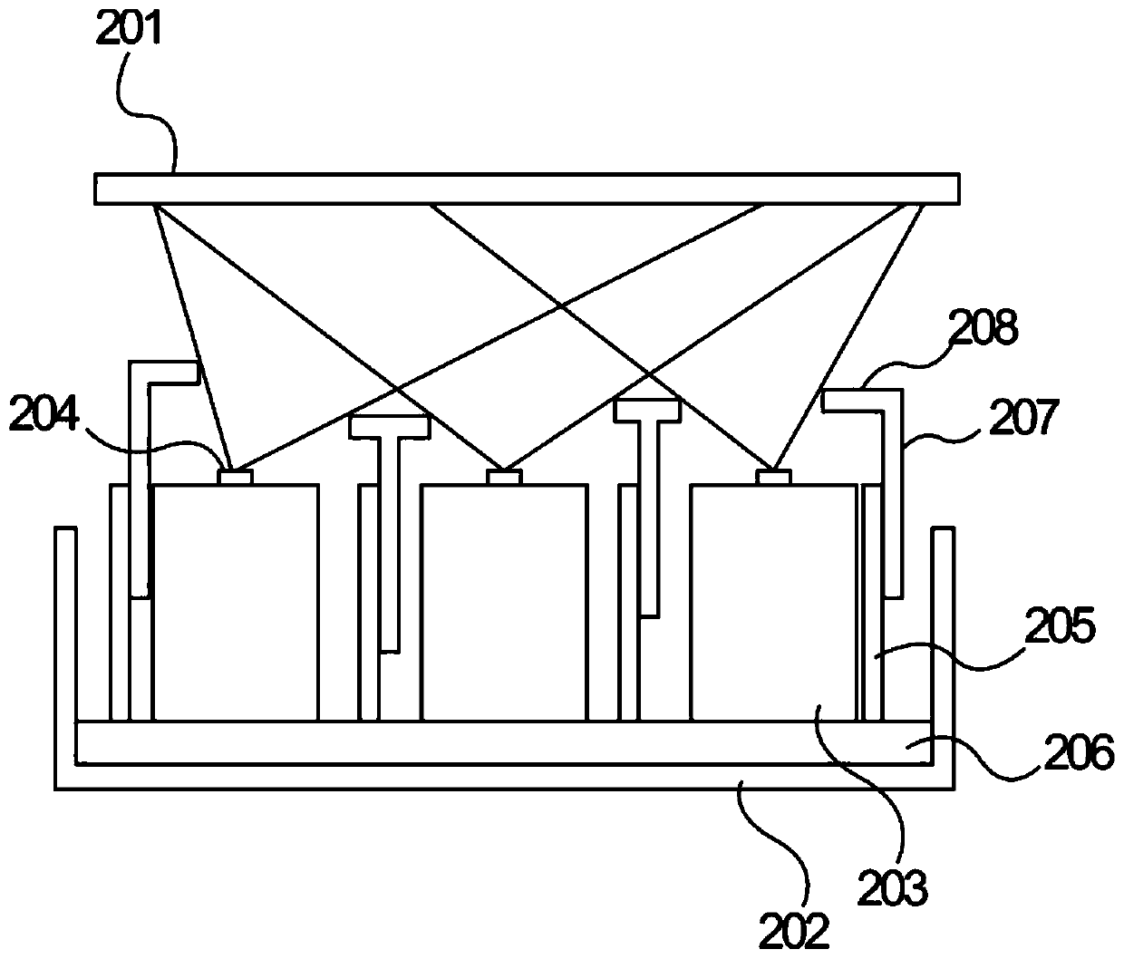
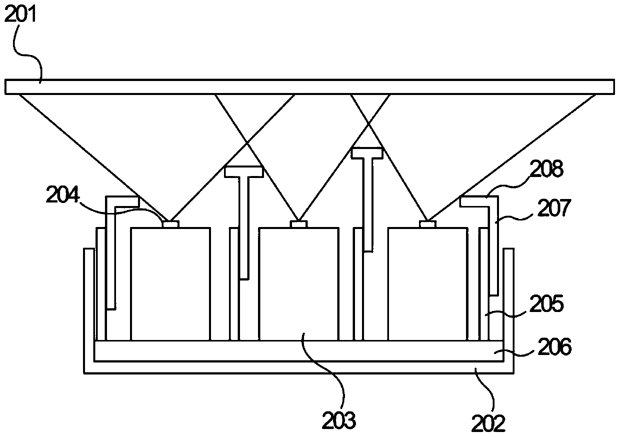
[0029] The present invention is aimed at the existing evaporation source device, the height and position of the limiting plate are fixed, and the spraying range of the nozzle is also fixed, which cannot meet the technical problem of adjusting the range of areas where different doping materials are deposited on the surface of the substrate. Embodiments can address this ...


PUM


Abstract

Provided is an evaporation device, comprising: a housing (202), and a plurality of evaporation sources (101, 203), which are located inside said housing (202) and used for evaporating a material to produce a gas material; the evaporation sources (101, 203) comprise: a material chamber, used for placing a material; a heating element, affixed to the exterior of the material chamber and used for heating the material inside the material chamber; nozzles (103, 204), located on the upper side of the evaporation sources (101, 203) and used for spraying the gas material onto the surface of a substrate (201); limit plates (102, 207), arranged on the two sides of the evaporation sources (101, 203); the height of the limit plates (102, 207) exceeds the nozzles (103, 204); the distance between adjacent limit plates (102, 207) is different from the height, and is used for limiting the range of material-spraying of the nozzles (103, 204) between two limit plates (102, 207); the limit plates (102, 207) are connected to a mobile assembly; by means of the mobile assembly, the limit plates (102, 207) are capable of moving between the areas of two evaporation sources (101, 203), and are used for adjusting the range of material-spraying of the nozzles (103, 204).

Description

technical field [0001] The invention specifically relates to an evaporation device. Background technique [0002] Compared with the current mainstream liquid crystal display technology, OLED display technology has outstanding advantages such as high contrast, wide color gamut, flexibility, thinness, and energy saving; Wearable devices, large-size curved TVs, white lighting and other fields are popularized, and the development momentum is strong. [0003] OLED technology mainly includes small molecule OLED technology based on vacuum evaporation technology and polymer OLED technology based on solution process; evaporation machine is the main equipment for the production of small molecule OLED devices that have been mass-produced at present, and the core part of the equipment It is an evaporation source device, which is divided into point evaporation source, line evaporation source, surface evaporation source and so on. [0004] In the existing evaporation source device, in o...

Claims


Application Information

Patent Timeline
Patent Type & Authority Patents(China)
IPC IPC(8): C23C14/24
CPCC23C14/24C23C14/243
Inventor 沐俊应
Owner WUHAN CHINA STAR OPTOELECTRONICS TECH CO LTD
Why Eureka
Try Eureka