
Board grabbing and putting mechanism for PCB board splitting machine

A technology for separating boards and placing racks, which is applied in the direction of conveyors, conveyor objects, electrical components, etc. It can solve the problems of affecting the yield, affecting the feeding efficiency, and low efficiency, and achieves high automation, convenient processing, and high efficiency. high effect

Active Publication Date: 2017-07-21
道县东圣电子科技有限公司
View PDF9 Cites 25 Cited by
  • Summary
  • Abstract
  • Description
  • Claims
  • Application Information

AI Technical Summary

Problems solved by technology

[0004] The existing PCB sub-boards generally use manual sub-boards, which have poor effect and low efficiency, and manual sub-boards are easy to damage the board and affect the yield, so mechanical sub-boards are now used;
[0005] However, in the existing mechanical sub-panels, the material is generally loaded manually, which needs to be manually taken from the material box, placed on the mold, and then fixed by the upper platen, which is very troublesome and greatly affects the efficiency of material loading. efficiency

Method used


Image

  • Board grabbing and putting mechanism for PCB board splitting machine
  • Board grabbing and putting mechanism for PCB board splitting machine
  • Board grabbing and putting mechanism for PCB board splitting machine

Examples


Embodiment Construction

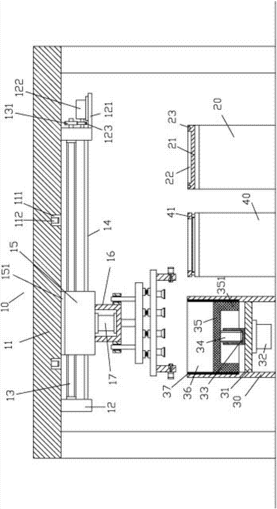
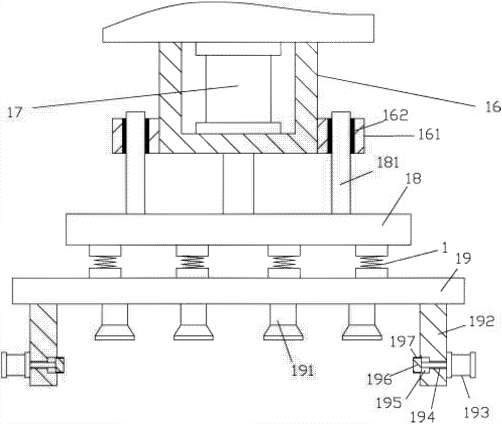
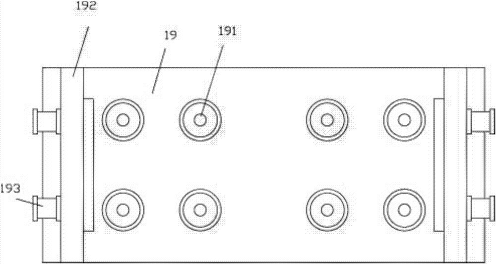
[0030] Examples, see e.g. Figure 1 to Figure 3 As shown, a grab board placement mechanism for a PCB splitter includes a grab frame 10, a placement rack 20, a sheet rack 30 and a platen frame 40, and the sheet frame 30 is located on the left side of the platen frame 40, and placed The frame 20 is at the right side of the platen frame 40, and the placement frame 20, the material plate frame 30 and the platen frame 40 are all below the upper top plate 11 of the grasping frame 10;

[0031] The middle part of described sheet rack 30 is fixed with intermediate partition 31, and the middle part of the bottom surface of intermediate partition 31 is fixed with lifting motor 32, and the output shaft of lifting motor 32 passes intermediate partition 31, and the top surface of the output shaft of lifting motor 32 The middle part has an adjusting screw hole 33, and the lifting screw 34 is screwed in the adjusting screw hole 33, and the top of the lifting screw 34 is fixed with a lifting p...


PUM


Abstract

The invention discloses a board grabbing and putting mechanism for a PCB board splitting machine. The board grabbing and putting mechanism comprises a grabbing rack, a placement frame, a board frame and a board pressing frame. The board frame is located on the left side of the board pressing frame, the placement frame is arranged on the right side of the board pressing frame, and the placement frame, the board frame and the board pressing frame are located below an upper top board of the grabbing rack. A middle partition board is fixed to the middle portion of the board frame. A lifting motor is fixed to the middle portion of the bottom face of the middle partition board. An output shaft of the lifting motor penetrates the middle partition board, an adjusting screw hole is formed in the middle portion of the top face of the output shaft of the lifting motor, a lifting threaded rod is screwed into the adjusting screw hole, a lifting board is fixed to the top end of the lifting threaded rod, and the lifting board is arranged in a feeding cavity in the upper portion of the board frame. The board grabbing and putting mechanism can automatically grab a board and a pressing board body, carry out feeding and install the board and the board pressing body on a lower template of the placement frame, following machining is facilitated, and the board grabbing and putting mechanism is high in automation degree and efficiency and good in effect.

Description

[0001] Technical field: [0002] The invention relates to the technical field of circuit board manufacturing and processing, and more specifically relates to a gripping plate placement mechanism for a PCB splitting machine. [0003] Background technique: [0004] The existing PCB sub-boards generally use manual sub-boards, which have poor effect and low efficiency, and manual sub-boards are easy to damage the board and affect the yield, so mechanical sub-boards are now used; [0005] However, in the existing mechanical sub-panels, the material is generally loaded manually, which needs to be manually taken from the material box, placed on the mold, and then fixed by the upper platen, which is very troublesome and greatly affects the efficiency of material loading. efficiency. [0006] Invention content: [0007] The purpose of the present invention is to overcome the deficiencies of the prior art, to provide a grab board placement mechanism for a PCB splitter, which can automa...

Claims


Application Information

Patent Timeline
Patent Type & Authority Applications(China)
IPC IPC(8): B65G47/91H05K3/00
CPCB65G47/912B65G2201/022H05K3/0052
Inventor 姜硕
Owner 道县东圣电子科技有限公司
Learn More