Bridge equipment

A technology of equipment and bridges, which is applied in the field of bridge equipment, can solve the problems of increasing operation steps and increasing equipment costs, and achieve the effect of reducing operation steps, reducing equipment costs, and reasonable design

Active Publication Date: 2017-07-21
泰兴市东城水处理工程有限公司
View PDF5 Cites 6 Cited by
  • Summary
  • Abstract
  • Description
  • Claims
  • Application Information

AI Technical Summary

Problems solved by technology

[0002] A bridge refers to a structure erected on rivers, lakes, and seas to allow vehicles and pedestrians to pass smoothly. In order to ensure safe passage, railings are installed on both sides of the bridge. There are many types of railings, including iron railings and cement slurry pouring. Railings, etc., wherein the railings made of cement slurry need to pour the cement slurry into the cavity of the model, so that the cement slurry can be directly installed on the bridge body after the cement slurry is poured into shape. To take it out of the model cavity, it usually needs to be pulled out with tools such as hooks, which increases the operation steps and increases the equipment cost

Method used


Image

  • Bridge equipment
  • Bridge equipment
  • Bridge equipment

Examples


Embodiment Construction

[0014] All features disclosed in this specification, or steps in all methods or processes disclosed, may be combined in any manner, except for mutually exclusive features and / or steps.

[0015] Any feature disclosed in this specification (including any appended claims, abstract and drawings), unless expressly stated otherwise, may be replaced by alternative features which are equivalent or serve a similar purpose. That is, unless expressly stated otherwise, each feature is one example only of a series of equivalent or similar features.

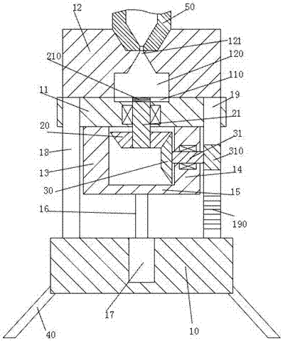
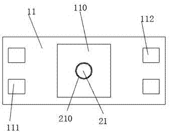
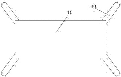
[0016] Such as Figure 1-3 As shown, a kind of bridge equipment of the present invention comprises a base plate 10, a fixed model frame 12, a sliding model frame 11 and a pouring head 50, four corners of the bottom of the base plate 10 are respectively provided with supporting feet 40, and the supporting feet 40 is fixedly connected with the bottom plate 10 and is inclined to open outwards. The left and right sides of the sliding model frame ...


PUM


Abstract

The invention discloses bridge equipment which comprises a bottom plate, a fixed model frame, a sliding model frame and a filling head. Supporting legs are arranged on the four corners of the bottom of the bottom plate. The supporting legs are fixedly connected with the bottom plate and areobliquely open outwards. Two left square guide grooves and two right square guide grooves are formed in the left side and the right side of the sliding model frame correspondingly. Left guide rods and right guide rods are slidably installed in the two left square guide grooves and the two right square guide grooves correspondingly. A left fixed connecting arm and a right fixed connecting arm are symmetrically and fixedly arranged on the left side and the right side of the lower end of the sliding model frame correspondingly. A combining arm is fixedly arranged at the lower ends of the left fixed connecting arm and the right fixed connecting arm. A connecting groove is formed in the middle point of the upper end of the fixed model frame. The filling head is installed in the connecting groove. A model cavity is formed in the fixed model frame. The bridge equipment is simple in structure, stable in operation and reasonable in design.

Description

technical field [0001] The invention relates to the field of bridge facilities, in particular to bridge equipment. Background technique [0002] A bridge refers to a structure erected on rivers, lakes, and seas to allow vehicles and pedestrians to pass smoothly. In order to ensure safe passage, railings are installed on both sides of the bridge. There are many types of railings, including iron railings and cement grout. Railings, etc., wherein the railings made of cement slurry need to pour the cement slurry into the cavity of the model, so that the cement slurry can be directly installed on the bridge body after the cement slurry is poured into shape. To take it out from the model cavity, it usually needs to be pulled out with tools such as hooks, which increases the operation steps and increases the equipment cost. Contents of the invention [0003] The object of the present invention is to provide a bridge device and its use method, which can overcome the above-mention...

Claims


Application Information

Patent Timeline
Patent Type & Authority Applications(China)
IPC IPC(8): E01D21/00
CPCE01D21/00
Inventor 黄陈凯
Owner 泰兴市东城水处理工程有限公司
Why Eureka
Try Eureka