Double-control thermostatic valve element

A thermostatic spool and spool technology, applied in the field of thermostatic valves, can solve problems such as complex waterway structure, affecting the overall appearance of the thermostatic faucet, and the overall structure of the thermostatic faucet.

Inactive Publication Date: 2017-07-21
吴小艇
View PDF0 Cites 14 Cited by
  • Summary
  • Abstract
  • Description
  • Claims
  • Application Information

AI Technical Summary

Problems solved by technology

This time, the overall structure of the thermostatic faucet is larger, and the waterway structure is more complicated, which will also affect the overall appearance of the thermostatic faucet.

Method used


Image

  • Double-control thermostatic valve element
  • Double-control thermostatic valve element
  • Double-control thermostatic valve element

Examples


Embodiment 1

[0039] Embodiment 1, a dual-control thermostatic valve core

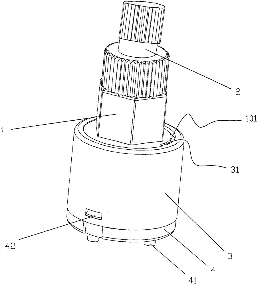
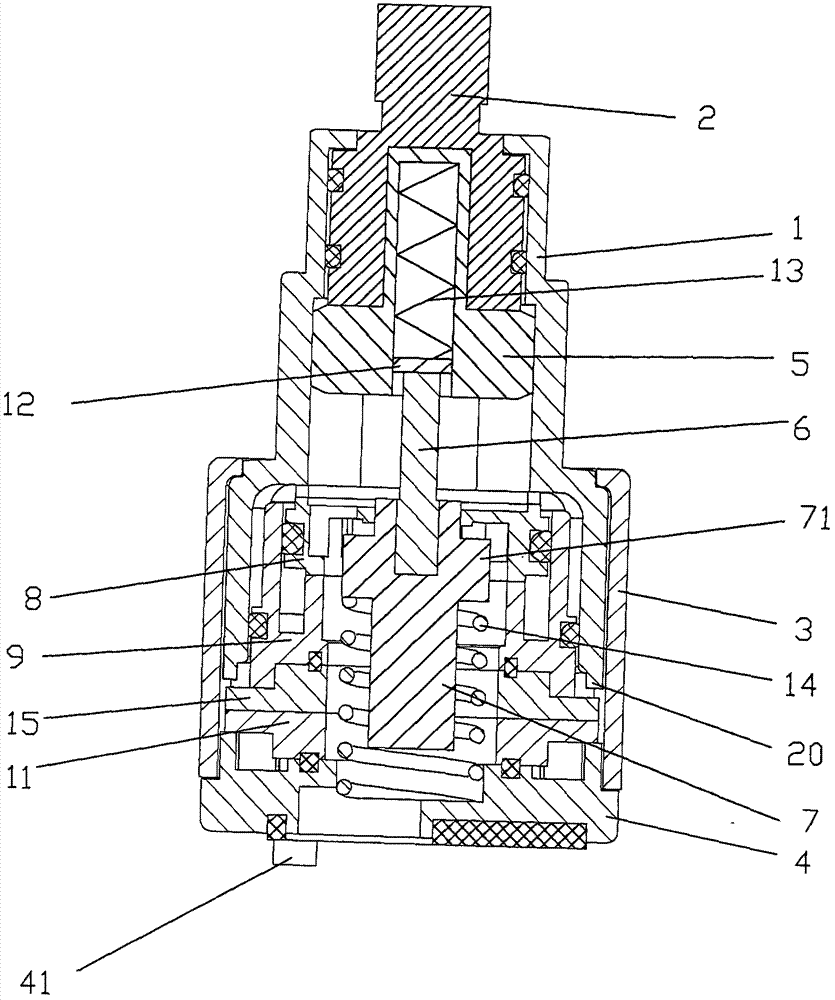
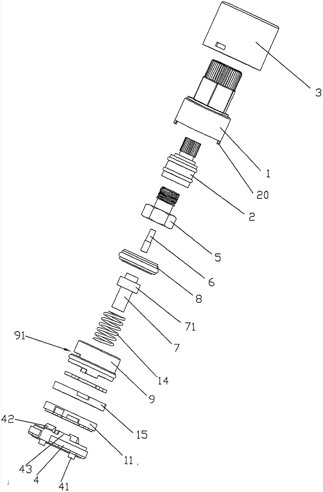
[0040] Such as Figure 1 to Figure 3 As shown, a dual-control thermostatic valve core includes an outer valve body 1, which is integrally injection-molded and has a stepped shape. The steps are divided into three stages, each step is circular, and the outer valve body 1 has a diameter of gradually increase from top to bottom. The outer valve body 1 is hollow inside and is used for installing a water temperature regulating mechanism. The water temperature adjustment mechanism includes an adjustment knob 2, a sliding block 5, a push rod 6, a water temperature adjustment valve core 8, a temperature sensing component and an inner valve body 9 installed in the outer valve body 1 sequentially from top to bottom. The upper end of the adjustment knob 2 protrudes from the outer valve body 1 , and the lower end is inside the upper end of the outer valve body 1 . A threaded hole is arranged at the center of the lower end of...

Embodiment 2

[0047] Embodiment 2, a dual-control thermostatic valve core

[0048] Such as Figure 13 As shown, the difference between Embodiment 2 and Embodiment 1 is that the temperature-sensing component of Embodiment 2 is a temperature-sensing spring 19 made of memory alloy, and the upper end of the temperature-sensing spring 19 is in conflict with the lower end surface of the water temperature regulating valve core 8, and the temperature-sensing spring 19 lower ends are in conflict with the base 4 upper surface. The elastic coefficient of the temperature sensing spring 19 is greater than that of the spring 13 . During use, cold water is passed into the water supply port 46, and hot water is passed into the water supply port 44, so that cold water flows out from the hot water flow channel outlet 97, and hot water flows out from the cold water flow channel outlet 91. When the hot water is cut off, the lower surface of the water temperature regulating valve core 8 is in conflict with th...

Embodiment 3

[0049] Embodiment 3, a dual-control thermostatic valve core

[0050] Such as Figure 13 As shown in Figure 14, the difference between the third embodiment and the first embodiment lies in the inner valve body 9 and the base 4. The lower end surface of the inner valve body 9 in the third embodiment is also provided with an annular extension section 910 , and the lower end of the extension section 910 is provided with a flange 911 opening toward the center of the extension section 910 . During installation, the lower end of the return spring 14 is in contact with the flange 911 at the lower end of the extension section 910 . Simultaneously, the upper surface of the base 4 is not provided with the mounting position of the back-moving spring 14, which can increase the co-flow area when the water is discharged and reduce the pressure loss.


PUM


Abstract

The invention discloses a dual-control thermostatic valve core, which comprises an outer valve body, the outer valve body is in the shape of steps, a water temperature adjustment mechanism is installed on the upper end of the outer valve body, and an inner valve body matched with the inner valve body is set on the lower end of the water temperature adjustment mechanism. The two sides of the lower end of the valve body are respectively provided with a cold water inlet and a hot water inlet. The inside of the inner valve body is provided with a cold water flow channel and a hot water flow channel separated from each other. There is a boss, the outlet of the hot water flow channel is set on the upper end of the boss, and the center of the inner valve body is provided with a mixing chamber for mixing hot and cold water. The water temperature adjustment mechanism includes a water temperature adjustment valve core, which is inserted in the mixing chamber It moves up and down under the effect of water temperature to adjust the ratio of cold water and hot water entering the mixing chamber to adjust the water temperature in the mixing chamber. The dual-control thermostatic valve core has a simple structure and can simultaneously adjust the outlet water temperature and the outlet water flow rate.

Description

technical field [0001] The invention relates to a thermostatic valve, in particular to a dual-control thermostatic valve core. Background technique [0002] The thermostatic spool is a commonly used device in high-end sanitary products. The original thermostatic valve core can only realize the control of the water temperature, but cannot realize the control of the outlet water flow. If it is necessary to realize the control of the outlet water flow of the thermostatic valve, it is necessary to add another on-off valve to control the outlet water flow. If such a thermostatic valve is installed in a thermostatic faucet, it is necessary to install another on-off valve to control the water flow. This time, the overall structure of the thermostatic faucet is larger, and the waterway structure is more complicated, which will also affect the overall appearance of the thermostatic faucet. Contents of the invention [0003] Aiming at the deficiencies in the prior art, the object...

Claims


Application Information

Patent Timeline
Patent Type & Authority Applications(China)
IPC IPC(8): F16K11/074F16K31/64
CPCF16K11/074F16K31/002
Inventor 吴小艇
Owner 吴小艇
Why Eureka
Try Eureka