Wound storage battery with symmetric composite electrodes and perforated collector plates

A composite electrode and collector plate technology, applied in the direction of lead-acid battery, lead-acid battery electrode, lead-acid battery construction, etc., can solve the problems of uneven current distribution, low current conduction capability, poor performance, etc. Method economy, mechanical strength and anti-vibration performance improvement, effect of reducing battery temperature

Inactive Publication Date: 2017-07-21
陈学琴
View PDF0 Cites 0 Cited by
  • Summary
  • Abstract
  • Description
  • Claims
  • Application Information

AI Technical Summary

Problems solved by technology

[0003] In order to overcome the defects of low current conduction capacity, high internal resistance, uneven current distribution during charging and discharging of the existing wound lead-acid batteries, and poor performance in applications requiring high-rate charging and discharging, this paper The invention provides a coiled storage battery with a symmetrical composite electrode and a porous collector disc, which can make the current distribution even during the charging and discharging process, effectively improve the current conduction capacity, improve the mechanical strength and anti-vibration performance of the electrode, and reduce the electrode load. Internal resistance, with high-rate charging and discharging characteristics of super capacitors, which improves the safety of the battery, prolongs the cycle life of the battery, and further improves the performance of the wound lead-acid battery

Method used


Image

  • Wound storage battery with symmetric composite electrodes and perforated collector plates
  • Wound storage battery with symmetric composite electrodes and perforated collector plates
  • Wound storage battery with symmetric composite electrodes and perforated collector plates

Examples


Embodiment Construction

[0018] The technical solution of the present invention will be further described below in conjunction with the accompanying drawings and specific embodiments.

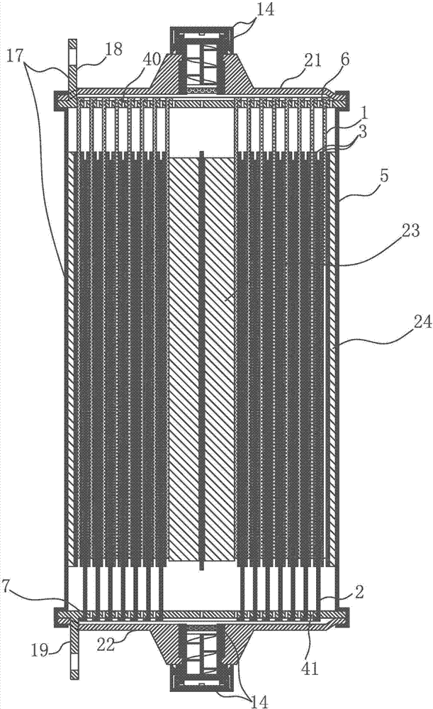
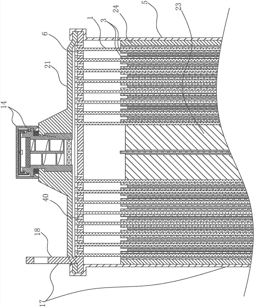
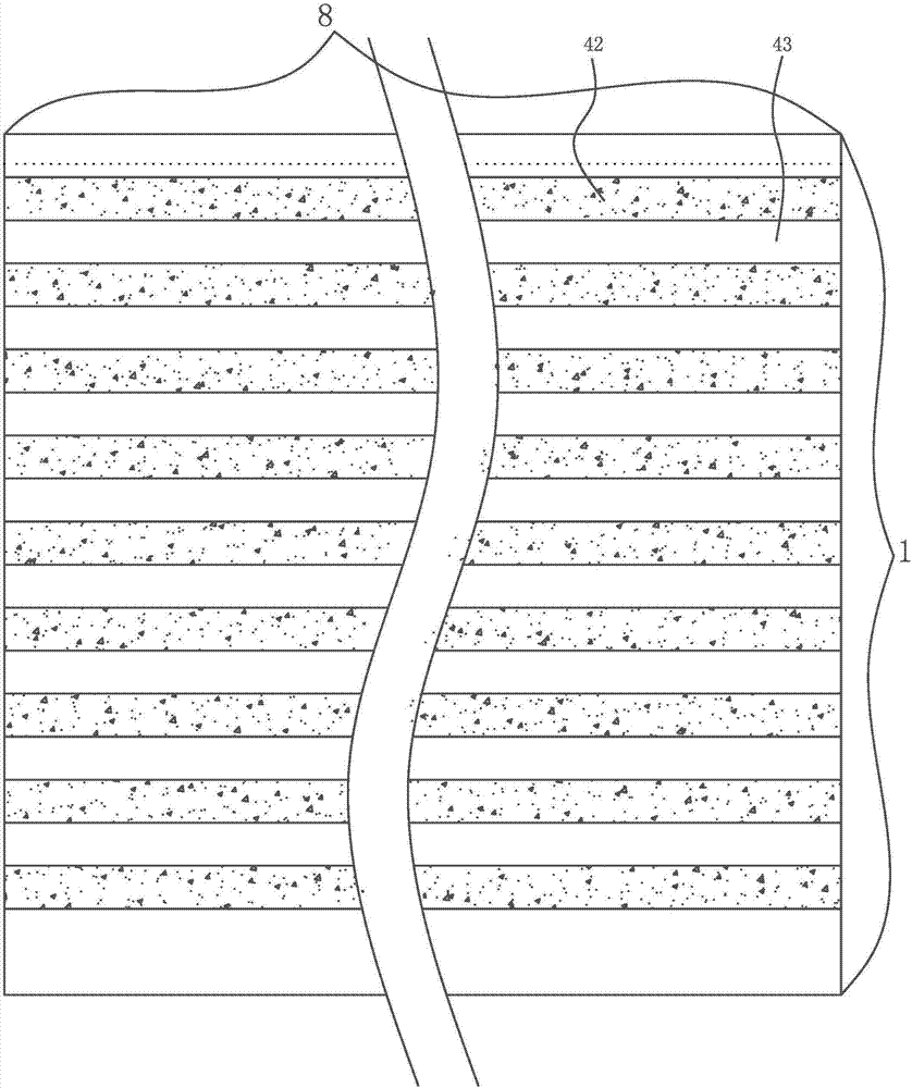
[0019] Such as Figure 1-9 As shown, a winding storage battery with a symmetrical composite electrode having a collector disc, comprising a battery casing (5) and a cell (33), is characterized in that: the cell (33) is composed of a positive electrode sheet (1), a negative electrode sheet ( 2) and the separator (3) positioned between the positive electrode sheet and the negative electrode sheet is wound into a columnar body by the battery core reel (23), and a positive electrode collector plate ( 6) and the negative current collecting plate (7); the positive electrode sheet (1) is provided with a positive electrode continuous lug (8 ); the negative pole piece (2) is provided with a pole lug (9) equal to the length of the negative pole piece (2) at the top of the negative pole current collecting plate (7); the positive...


PUM


Abstract

The invention provides a wound storage battery with symmetric composite electrodes and perforated collector plates. The wound storage battery comprises a battery case and a battery core; the wound storage battery is characterized in that the battery core is a cylindrical body formed by winding a positive plate, a negative plate and a membrane located between the positive plate and the negative plate through a battery core reel; a positive collector plate and a negative collector plate are arranged at the tops of two ends of the battery core separately; a tab, namely a positive continuous tab, which is equal to the positive plate in length is arranged at the top end of one side, close to the positive collector plate, of the positive plate; a spiral groove body, namely a positive plate clamping groove is arranged in the corresponding collector plate; the positive plate and the negative plate are composite electrodes and are constructed by arranging a metal oxide coating distributed in a strip on a lead plate as a bottom plate; and metal oxide coating materials such as ruthenium oxide and the like distributed in a strip are arranged on the lead plate. The wound storage battery has the beneficial effects that the current conducting capability is effectively improved through unique end-surface collector structures and composite electrodes, and meanwhile, the battery has high-rate charging and discharging characteristics of a super-capacitor.

Description

technical field [0001] The invention relates to a lead-acid storage battery, in particular to a high-power, high-rate discharge wound lead-acid super storage battery, which belongs to the technical field of storage battery processing and manufacturing. Background technique [0002] At present, most of the traditional winding lead-acid batteries use single or multiple tabs as the current collection method. During the discharge process, the current distribution is uneven, and it is difficult to realize high-current charge and discharge. In addition, when charging and discharging with high current, due to the large internal resistance of the battery, it will cause serious heating and the battery temperature is too high, which will cause safety hazards; Charge and discharge use cases do not perform well. Contents of the invention [0003] In order to overcome the defects of low current conduction capacity, high internal resistance, uneven current distribution during charging...

Claims


Application Information

Patent Timeline
Patent Type & Authority Applications(China)
IPC IPC(8): H01M2/26H01M2/28H01M4/14H01M10/12H01M10/14H01M50/538H01M50/541
CPCH01M4/14H01M10/12H01M10/125H01M10/14H01M50/538H01M50/541Y02E60/10Y02P70/50
Inventor 陈学琴
Owner 陈学琴
Why Eureka
Try Eureka