
Flexible die releasing method of closed die forging large irregular profile structure forge piece

A closed die forging, large-scale technology, applied in forging/pressing/hammer devices, forging/pressing/hammering machinery, manufacturing tools, etc., can solve the problems of forging deformation, tearing, unbalanced force, etc., to reach the peak The effect of smooth process

Active Publication Date: 2017-07-25
贵州锆石科技发展有限责任公司
View PDF4 Cites 10 Cited by
  • Summary
  • Abstract
  • Description
  • Claims
  • Application Information

AI Technical Summary

Problems solved by technology

[0004] It can be seen from this that when a rigid ejector pin is used to eject a forging, as the ejection force continues to increase, some parts will loosen first, detach and then be stressed again, and the loose parts will be affected by gap or pulse superimposed force. The overall force of the forging is unbalanced; and the ejection force and friction resistance of the forging part after re-stressing cannot be well matched, and it is affected by factors such as the depth of the mold cavity, the size of the contact area, the degree of lubrication, and the strength of the material. The demoulding process of forgings is not stable, which may easily cause deformation, warping, partial collapse and even tearing of forgings.

Method used


Image

  • Flexible die releasing method of closed die forging large irregular profile structure forge piece
  • Flexible die releasing method of closed die forging large irregular profile structure forge piece
  • Flexible die releasing method of closed die forging large irregular profile structure forge piece

Examples


Embodiment Construction

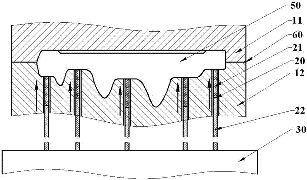
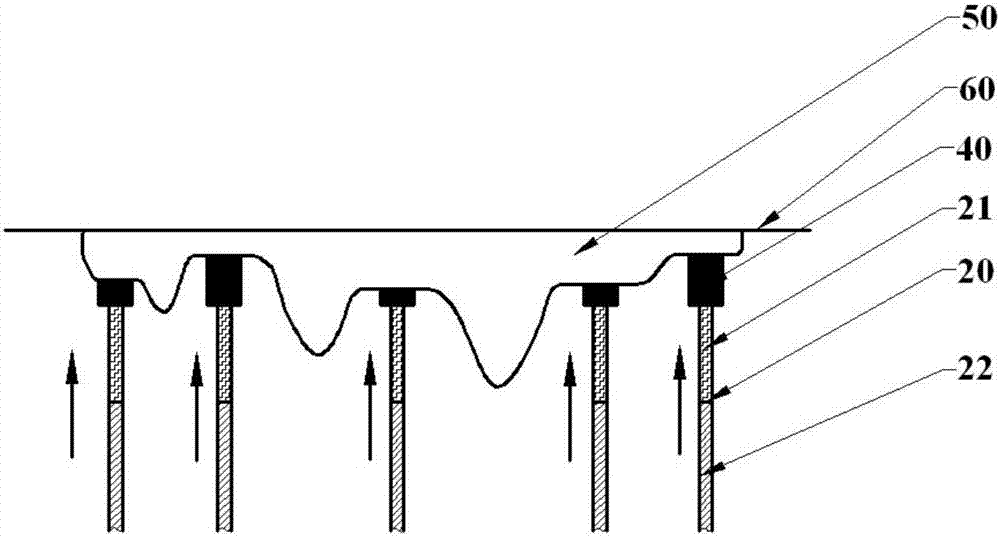
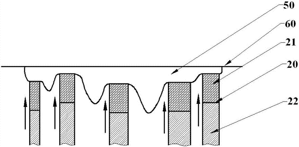
[0038] The schematic diagram of the first demoulding device adopted in the flexible demoulding method of the present invention is as follows figure 1 As shown, the demoulding device is mainly composed of five ejector pins 20 and a base 30 . After the large-scale special-shaped structure forging 50 is formed, it is in the mold cavity surrounded by the upper forging die 11 and the lower forging die 12. There is a parting surface 60 between the upper forging die 11 and the lower forging die 12. The lower forging die 12 There are 5 through holes in the center, the lower ends of the 5 push rods 20 are fixed on the base 30, and the upper ends pass through the through holes of the lower forging die 12 to contact with different bottom surfaces of the large special-shaped structure forgings 50, and each push rod 20 is formed by The flexible segment 21 that the upper end elastic material is made of and the rigid segment 22 that the lower end rigid material is formed constitute, that is ...


PUM

PropertyMeasurementUnit
Diameteraaaaaaaaaa
Lengthaaaaaaaaaa

Abstract

The invention discloses a flexible die releasing method of a closed die forging large irregular profile structure forge piece. The flexible die releasing method comprises the steps that an upper forging die is taken out firstly and then force is applied to pushing rods to push up the large irregular profile structure forge piece in a lower forging die; flexible sections of each pushing rod are compressed to the elastic limit, and the compression amount is equal; when push-out force of a certain pushing rod is larger than frictional resistance of the position, located on the pushing rod, of the forging piece and a die mold cavity, the position of the forging piece loosens firstly and produces certain displacement, the pushing rod is not separated from the forging piece, the situation same with the just pushing rod occurs gradually on the other one pushing rod or the other multiple pushing rods, and the process occurs randomly and is conducted continuously; and when the total push-out force of all the pushing rods is larger than the total frictional resistance of the forging piece, the forging piece loosens overall, bears relatively-even force and is steadily pushed out of the die mold cavity. According to the flexible die releasing method, the die releasing process of the forging piece becomes steadier and is not liable to damage, and the flexible die releasing method is mainly used for die releasing after forging of forging pieces such as large aircraft structural pieces.

Description

technical field [0001] The invention relates to a demoulding method for a forging, in particular to a flexible demoulding method for a closed-die forging of a large special-shaped structure forging. Background technique [0002] In the closed die forging metal material forming process such as isothermal forging and hot die forging, the metal material flows in the mold under the action of external force and fills the mold cavity to form a forging, while the metal generates friction with the surface of the mold cavity during the flow process. And form a new surface, if the lubrication is poor, the forging often sticks tightly to the mold, and a demoulding device is needed to eject the forging from the mold cavity when the forging is demolded. In the prior art, for large-scale special-shaped structural forgings with irregular shapes, such as large aircraft structural parts, the ejector rod of the demoulding device used after closed die forging is made of rigid materials, and at...

Claims


Application Information

Patent Timeline
IPC IPC(8): B21J13/14
CPCB21J13/14
Inventor 吴浩
Owner 贵州锆石科技发展有限责任公司
Learn More