Oxygen-nitrogen separation housing of oxygen generator

A nitrogen-oxygen separation and oxygen generator technology, which is applied in specific gas purification/separation, oxygen/ozone/oxide/hydroxide, inorganic chemistry, etc. The effect of stable oxygen, increasing the number of liters of oxygen output, and increasing the rate of oxygen output

Pending Publication Date: 2017-07-25
崔泽龙
View PDF0 Cites 3 Cited by
  • Summary
  • Abstract
  • Description
  • Claims
  • Application Information

AI Technical Summary

Problems solved by technology

There are relatively few multi-column generators, and the disadvantages

Method used


Image

  • Oxygen-nitrogen separation housing of oxygen generator

Examples


Example Embodiment

[0015] Embodiments of the technical solutions of the present invention will be described in detail below in conjunction with the accompanying drawings. The following examples are only used to illustrate the technical solutions of the present invention more clearly, and therefore are only examples, rather than limiting the protection scope of the present invention.

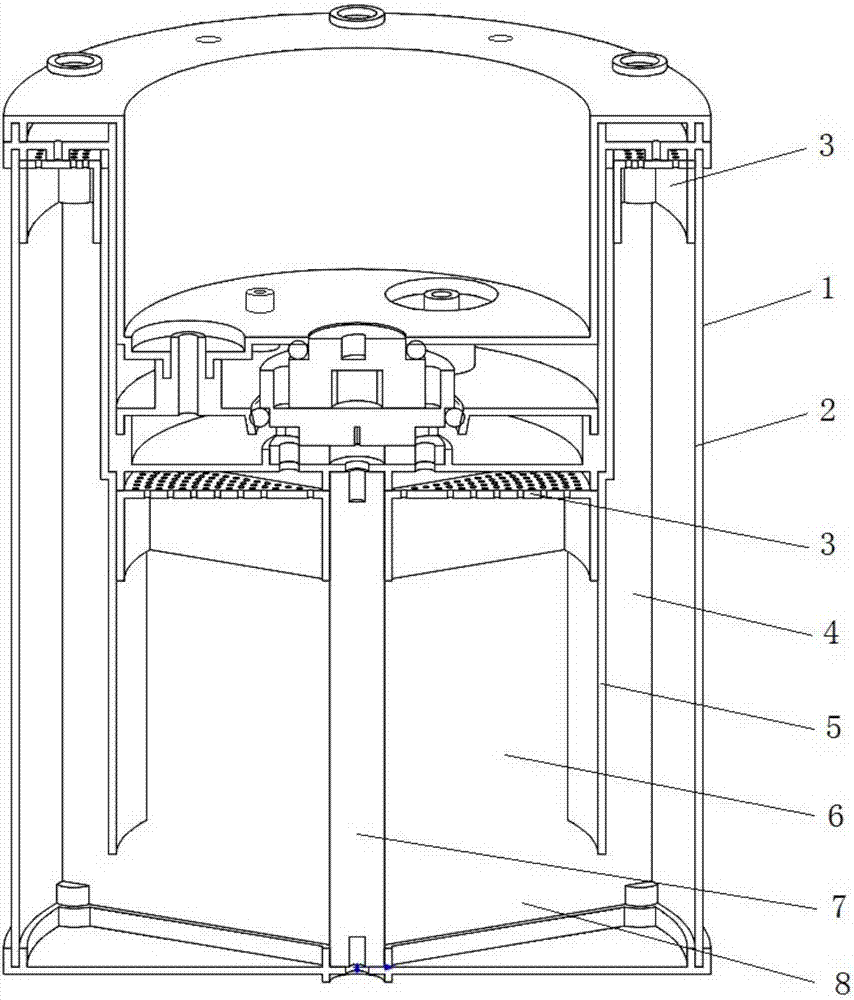
[0016] like figure 1 Shown: the nitrogen and oxygen separation casing of the oxygen generator in this embodiment, including a separation cylinder 1 and a molecular sieve (not shown in the figure); the lower end of the separation cylinder 1 is closed, and a plurality of radial partitions are arranged in the separation cylinder 1 8 and isolate the inner cavity of the separation cylinder 1 into a plurality of fan-shaped cavities arranged in the circumferential direction through radial partitions 8; the molecular sieves (not shown) are filled in each fan-shaped cavity, and each fan-shaped cavity forms a Nitrogen and o...


PUM


Abstract

The invention discloses a nitrogen-oxygen separation casing for an oxygen generator, which includes a separation cylinder and a molecular sieve; Cavity isolation is a plurality of fan-shaped cavities arranged along the circumferential direction; the molecular sieves are filled in each fan-shaped cavity, and the nitrogen and oxygen separation shell of the oxygen generator of the present invention adopts an equal-divided cylindrical structure, which is characterized by integral molding and sufficient space utilization , the size of the molecular sieve is increased, and the U-shaped circuit solves the defect of the large volume of the generator.

Description

technical field [0001] The invention relates to the technical field of nitrogen and oxygen separation, in particular to a nitrogen and oxygen separation shell of an oxygen generator. Background technique [0002] The main components of air are nitrogen (78%) and oxygen (21%). Therefore, it can be said that air is an inexhaustible source of nitrogen and oxygen. Nitrogen is mainly used for ammonia synthesis, protective atmosphere for metal heat treatment, inert protective gas in chemical production (pipeline purge when starting and stopping, nitrogen seal for easily oxidized substances, pressing materials), grain storage, fruit preservation and electronic industry, etc. Oxygen is mainly used as an oxidant in metallurgy, gas-supporting, medical treatment, wastewater treatment and chemical industry. How to cheaply separate air to produce oxygen and nitrogen is a problem that chemical workers have devoted themselves to research and solve for a long time. PSA is the pressure swi...

Claims


Application Information

Patent Timeline
IPC IPC(8): C01B13/02
CPCC01B13/0259C01B2210/0046C01B2210/0014
Inventor 崔泽龙
Owner 崔泽龙
Why Eureka
Try Eureka