Resonance hydrogen and oxygen generator

A hydrogen-oxygen machine and voltage technology, applied in the field of hydrogen-oxygen machines, can solve the problems of low oxygen production capacity, slow gas production, high temperature, etc., and achieve the effect of improving efficiency

Inactive Publication Date: 2015-01-21
凃杰生 +1
View PDF4 Cites 0 Cited by
  • Summary
  • Abstract
  • Description
  • Claims
  • Application Information

AI Technical Summary

Problems solved by technology

But the electrolyzer box 20 of this oxygen hydrogen machine uses copper metal rod 21 as electrode, its ability of producing oxygen is not high originally, and the power processing of current electrolysis circuit 10 is to make electrolyzer box 20 form the effect of current electrolysis, because Current electrolysis P=I 2 R, only half of the maximum power transfer produces gas, and the other half produces heat (boiling water), so energy consumption, slow gas production, and high temperature must be cooled, and the volume is also large. In addition, the controller S of the current electrolysis (namely S 1 , S 2 , S 3 , S 4 ) can only be controlled in sections, which makes it difficult to control the gas output; therefore, if the current hydrogen-oxygen machine cannot solve the above-mentioned deficiencies and problems, it is bound to still fail to make the internal combustion engine obtain good efficiency and performance

Method used


Image

  • Resonance hydrogen and oxygen generator
  • Resonance hydrogen and oxygen generator
  • Resonance hydrogen and oxygen generator

Examples


Embodiment Construction

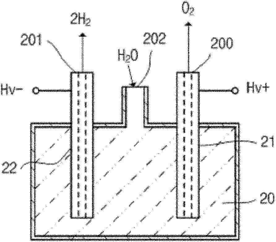
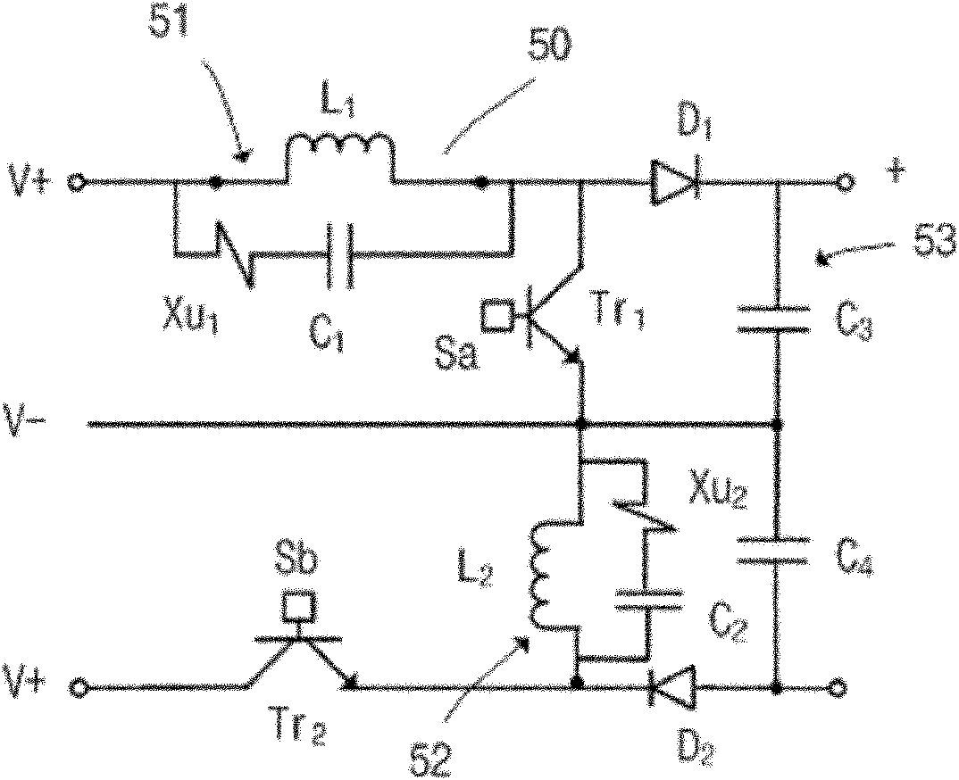
[0033] A resonant oxyhydrogen machine, such as image 3 , 4 , which includes an electrolytic tank 60 and at least one group of voltage electrolysis circuits 50; the group of voltage electrolysis circuits 50 is electrically connected to the battery power supply, and the group of voltage electrolysis circuits 50 has a first infinitely resonant chamber 51 and a first transistor Tr 1 electrically connected, and a second transistor Tr 2 It is electrically connected with a second infinite resonance chamber 52, and the first infinite resonance chamber 51 is connected with a first transistor Tr 1 and the second transistor Tr 2 Connected in parallel with the second infinite resonance chamber 52, the group of voltage electrolysis circuits 50 is also provided with a buffer circuit 53 as the two-pole input end of the electrolysis tank 60; the two terminals electrically connected to the voltage electrolysis circuit 50 of the electrolysis tank 60 are positive Extreme and negative end, i...


PUM


Abstract

The invention discloses a resonance hydrogen and oxygen generator, which comprises an electrolytic bath and at least one voltage electrolyzing circuit. Each of the voltage electrolyzing circuits is electrically connected with a battery supply and at least provided with a first infinite-stage resonance chamber, a first transistor, a second transistor and a second infinite-stage resonance chamber, wherein each first infinite-stage resonance chamber and the corresponding first transistor are electrically connected, each second transistor and the corresponding second infinite-stage resonance chamber are electrically connected, and a loop of the first infinite-stage resonance chamber and the corresponding first transistor is connected with a loop of the corresponding second transistor and the corresponding second infinite-stage resonance chamber in parallel. Further, each of the voltage electrolyzing circuits is provided with a buffering loop serving as a bipolar-electrode input end of the electrolytic bath. The two electrode ends, which are electrically connected with each of the voltage electrolyzing circuits, of the electrolytic bath, are a positive electrode end and a negative electrode end, the positive electrode end is a zinc oxide bar which is inserted into one end of the inside of a body of the electrolytic bath and is opposite to an oxygen outlet, the negative electrode end is a carbon bar which is inserted into the other end of the inside of the body of the electrolytic bath and is opposite to a hydrogen outlet, and the electrolytic bath is further provided with a water inlet. The resonance hydrogen and oxygen generator is capable of saving electricity and quickly generating gas at low temperature, and gas yield can be controlled.

Description

technical field [0001] The invention relates to an oxygen-hydrogen machine, in particular to a resonant oxygen-hydrogen machine. Background technique [0002] In the field of electrochemical industrial technology, the hydrogen and oxygen produced by the hydrogen-oxygen machine can be provided to the internal combustion engine to generate energy or power. The gas production speed, gas production and gas output of the hydrogen-oxygen machine will affect the working efficiency of the internal combustion engine and efficacy. [0003] Currently used hydrogen oxygen machine, such as figure 1 , 2 , which includes a group of current electrolysis circuits 10 and an electrolyzer box 20; the group of current electrolysis circuits 10 is electrically connected to a DC power supply 30, and the group of current electrolysis circuits 10 has a plurality of transistors Q triggered by a controller S in parallel. 1 , Q 2 , Q 3 , Q 4 It is electrically connected with an inductance coil L, ...

Claims


Application Information

Patent Timeline
Patent Type & Authority Patents(China)
IPC IPC(8): C25B1/04C25B9/00
CPCY02E60/366Y02E60/36
Inventor 徐夫子
Owner 凃杰生
Why Eureka
Try Eureka