a quenching machine

A quenching machine, an organic technology, applied in the field of quenching machines for thread quenching processing, can solve the problems of large volume of quenching machine tools, low quenching efficiency, inflexible movement of quenching mechanisms, etc., to achieve good quenching effect, high quenching efficiency, and labor-saving moving mode and stable effect

Active Publication Date: 2019-02-22
ZHOUSHAN 7412 FACTORY
View PDF6 Cites 0 Cited by
  • Summary
  • Abstract
  • Description
  • Claims
  • Application Information

AI Technical Summary

Problems solved by technology

However, the quenching machine tool has a large volume. Since the quenching mechanism is connected with the moving mechanism and the rotating mechanism, the movement of the quenching mechanism is inflexible and the quenching efficiency is low. Therefore, the structure of the device needs further improvement

Method used


Image

  • a quenching machine
  • a quenching machine
  • a quenching machine

Examples


Embodiment Construction

[0025] The present invention will be further described in detail below in conjunction with the accompanying drawings and embodiments.

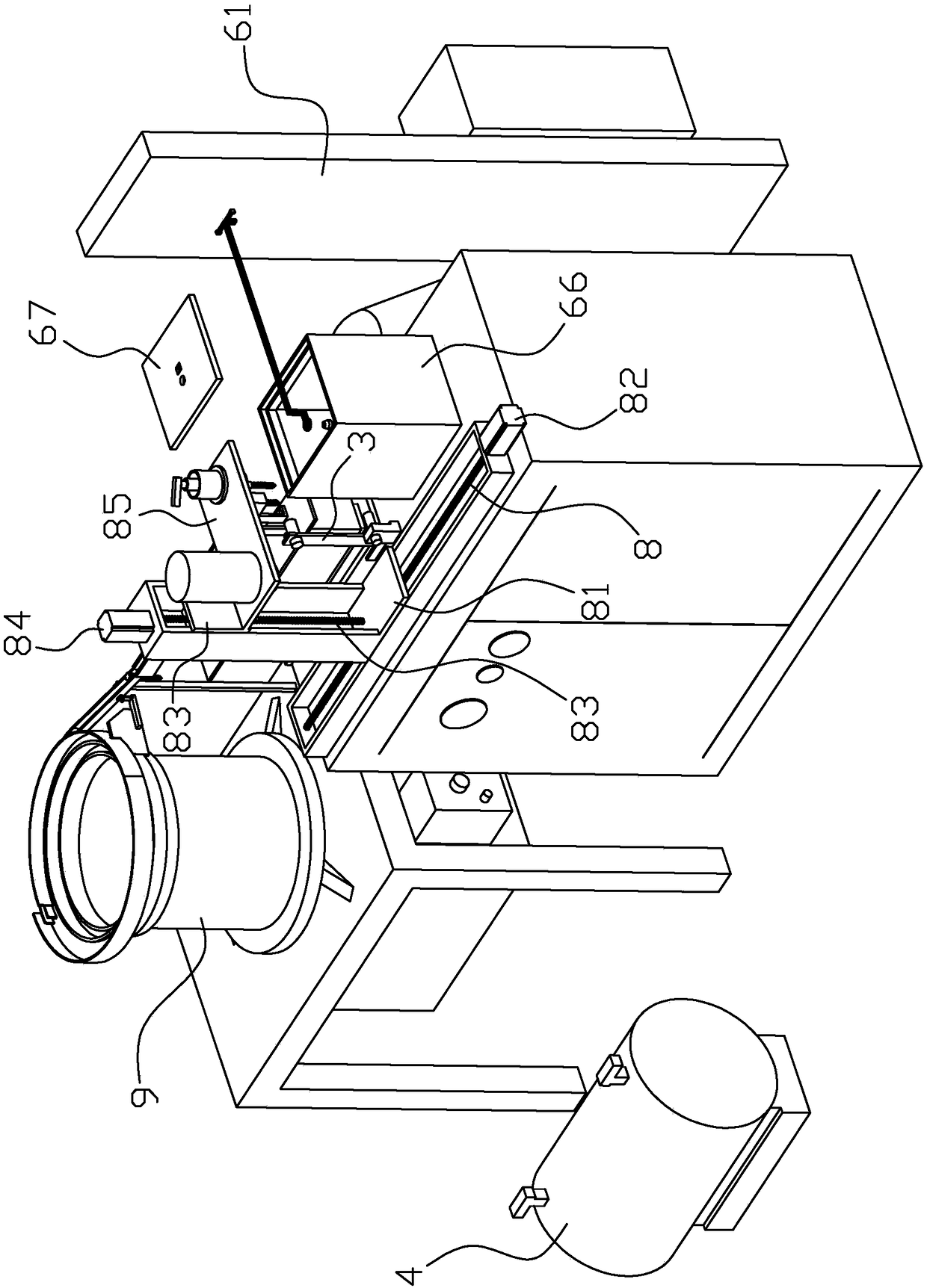
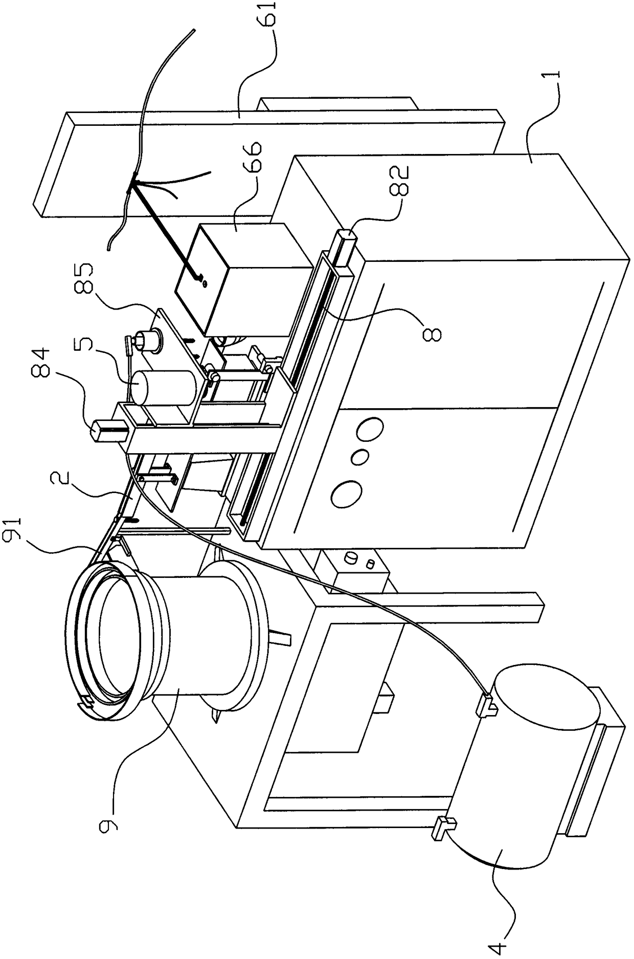
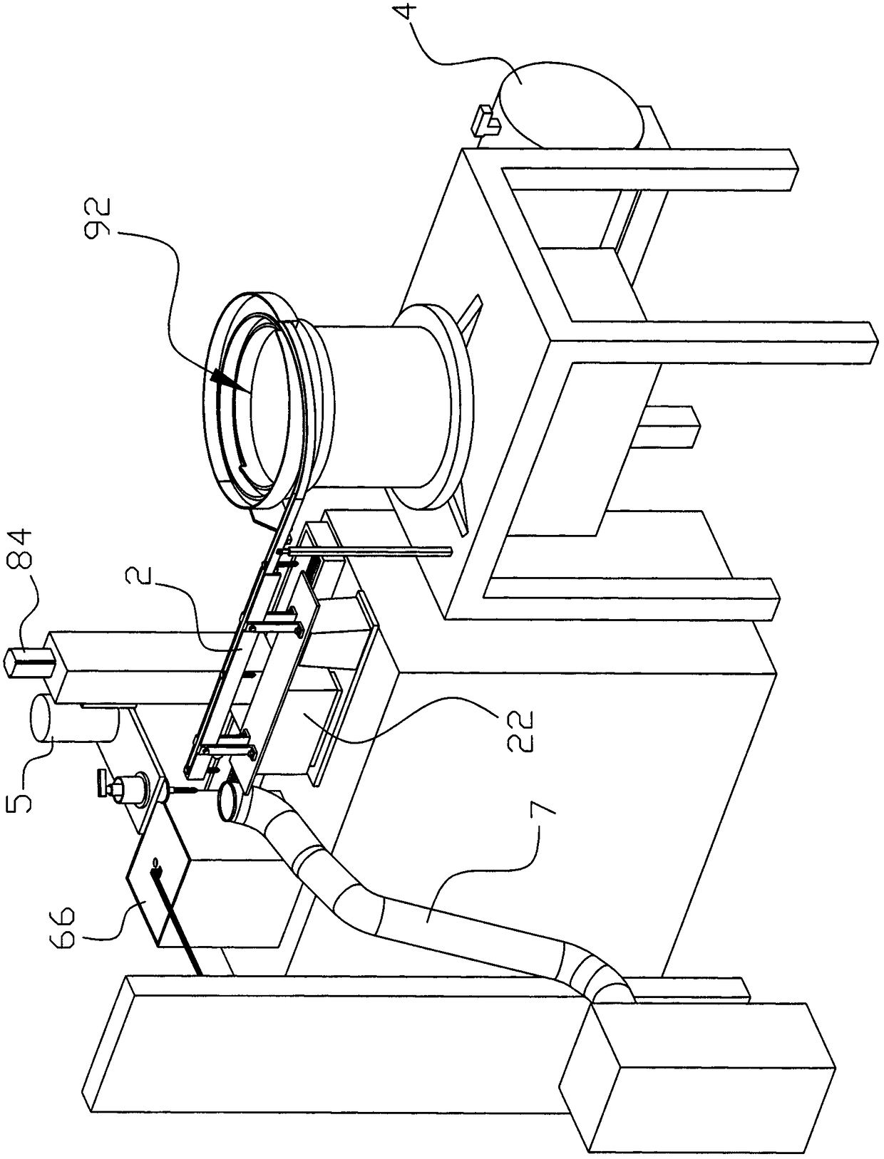
[0026] Such as Figure 1 to Figure 10 As shown, the quenching machine of the present embodiment includes a frame 1, and the frame 1 is provided with a slide rail 2 into which bolts or screws 21 slide, and one end of the slide rail 2 is provided with a frame to prevent the bolts or screws 21 from sliding. Out of the baffle plate of the slide rail 2, the frame 1 on one side of the baffle plate is provided with a position detection device 3 capable of detecting whether there are bolts or screws 21 in contact with the baffle plate, and the frame on the side of the slide rail 2 1 is provided with a movable arm that can move up, down, left, and right relative to the slide rail 2. The end of the movable arm is provided with an adsorption device capable of sucking the bolt or screw 21 from the slide rail 2. The adsorption device passes through the pip...


PUM


Abstract

The invention discloses a quenching machine. The quenching machine comprises a frame; the frame is provided with a slide rail for enabling a bolt or a screw to slide in; a baffle plate is arranged at one end of the slide rail; a position detecting device is arranged on the frame on one side of the baffle plate; a mobile arm capable of moving up and down and left and right corresponding to the slide rail is arranged on the frame on one side of the slide rail; an absorbing device capable of sucking the bolt or the screw from the slide rail is arranged at the end part of the mobile arm, and communicates with a vacuum pump through a pipe; a turntable capable of driving the bolt or the screw to horizontally rotate corresponding to the mobile arm is arranged at the bottom of the absorbing device, and is connected with a rotating motor capable of driving the turntable to rotate; the mobile arm absorbed with the bolt or the screw shifts the bolt or the screw into a quenching coil of a quenching part for quenching; after the quenching is finished, the mobile arm positions the bolt or the screw into a collecting pipe for collection; and the mobile arm, the rotating motor, the position detecting device, the vacuum pump and the quenching part are connected with a control circuit through leads. The quenching machine has the advantages of simple structure, high quenching efficiency and good quenching effect.

Description

technical field [0001] The invention relates to a quenching device, in particular to a quenching machine for thread quenching. Background technique [0002] There is an existing Chinese invention patent with the patent number CN201210242952.5 titled "A Quenching Machine Tool with a Rotary Quenching Mechanism", which discloses a machine tool, in particular to a quenching machine tool. The existing quenching machine tool has high cost and low precision. The invention provides a quenching machine tool with a rotary quenching mechanism, the rotary quenching mechanism is arranged on the beam of the machine tool, and the quenching mechanism can move left and right, up and down, and the feature is that a rotary mechanism is provided in the rotary quenching mechanism Between the quenching transformer and the quenching coil, the rotating mechanism can make the quenching coil rotate freely. The mechanism of the invention is simple, and the quenching mechanism is controlled to quench...

Claims


Application Information

Patent Timeline
Patent Type & Authority Patents(China)
IPC IPC(8): C21D1/667C21D9/00
CPCC21D1/667C21D9/0093
Inventor 王忠新杨培清潘立祖洪朋璐
Owner ZHOUSHAN 7412 FACTORY
Why Eureka
Try Eureka