Clearance eliminating device for gear pair

A technology of gear pair and clearance, applied in the direction of transmission parts, belt/chain/gear, mechanical equipment, etc., can solve the problems of inability to automatically compensate, unstable spring preload, inconvenient adjustment, etc., to reduce cutting chatter. Vibration and transmission error, solve the lack of spring force stiffness, solve the effect of inconvenient adjustment

Active Publication Date: 2017-07-25
HENAN INST OF ENG
View PDF4 Cites 4 Cited by
  • Summary
  • Abstract
  • Description
  • Claims
  • Application Information

AI Technical Summary

Problems solved by technology

[0002]In the field of mechanical technology, some transmission equipment needs to meet strict transmission ratio, and the error should be as small as possible, such as the feed mechanism transmission system of some precision machine tools Due to the manufacturing error and installation error of the gear transmission pair or worm pair, or the accumulation of time, the wear between the transmission pairs is intensified, resulting in an increasing gap between the transmission parts, which affects the efficiency and efficiency of the transmission. The precision of machining and manufacturing, at this time, it is necessary to solve this problem by eliminating the transmission gap
[0003] At present, it is mainly considered from the following aspects, which can be adjusted by staggering the teeth, changing the center distance, splitting the gear and adding elastic parts, and using the double-lead worm These methods either eliminate the backlash by changing the radial or axial distance of the gear pair, or use the elastic force of the spring to compress the paired tooth surface. These methods are all mechanical clearance methods. All have similar defects, such as in the transmission process, the spring preload is unstable, the tooth surface cannot be automatically compensated after the tooth surface is worn, and the adjustment is inconvenient, etc.

Method used


Image

  • Clearance eliminating device for gear pair
  • Clearance eliminating device for gear pair
  • Clearance eliminating device for gear pair

Examples


Embodiment 1

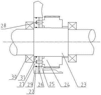
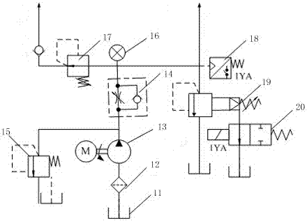
[0020] Embodiment one: see figure 1 and image 3 A gear pair backlash elimination device of the present invention includes a transmission shaft 24, a driven gear 23 fixedly arranged on the transmission shaft 24, and a hydraulic system, and the left side of the driven gear 23 is sequentially provided with a friction damping disc 25 and a Back cover two 27, an oil chamber is arranged between the friction damping disc two 25 and the back cover two 27, and the outer peripheral wall of the friction damping disc two 25 and the back cover two 27 is sleeved with a gear box body two 29. The gear box body 2 29 is provided with an oil port 26 connected to the oil chamber. When the pressure oil enters the oil chamber between the rear cover 27 and the friction damping disc 25 through the oil port 26, the friction The second damping disc 25 is subjected to a constant pressure from the pressure oil to the right, and the right end surface of the friction damping disc 25 is tightly attached t...

Embodiment 2

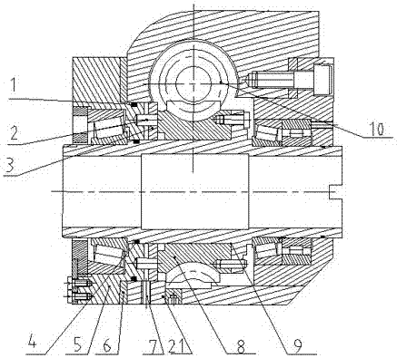
[0031] Embodiment two, see figure 2 and image 3 , a gear pair backlash elimination device of the present invention, comprising a worm gear shaft 9, a worm gear 8 fixedly arranged on the worm gear shaft 9, a worm screw 10 arranged above the worm gear 8 and meshed with the worm gear, and a hydraulic system, the worm gear 8 Friction damping disc-3 and rear cover-5 are arranged in sequence on the left side of the left side, an oil cavity is arranged between the friction damping disc-3 and rear cover-5, and the friction damping disc-3 and rear cover-5 The outer peripheral wall of the casing is provided with a gear box body-21, and the gear box body-21 is provided with an oil port-7 connected to the oil chamber. When the pressure oil enters the back cover-5 from the oil port-7 and friction Behind the oil chamber between the damping disc-3, the friction damping disc-3 is subjected to a constant pressure from the pressure oil to the right, and the right end surface of the friction ...


PUM


Abstract

The invention relates to the technical field of mechanical transmission manufacturing, in particular to a clearance eliminating device for a gear pair. The clearance eliminating device for the gear pair comprises a transmission shaft, a driven gear fixedly arranged on the transmission shaft, and a hydraulic system. A frictional damping disc and a rear cover are sequentially arranged on the left side of the driven gear. An oil cavity is formed between the frictional damping disc and the rear cover. A gearbox casing is located on the outer circumferential walls of the frictional damping disc and the rear cover. An oil port connected with the oil cavity is formed in the gearbox casing. According to the clearance eliminating device for the gear pair, hydraulic damping force is generated by the hydraulic system, and the driven gear in the gear pair is under the effect of frictional resistance in the transmission process, so that additional force is generated between tooth sides of the gear pair, and it is guaranteed that meshing teeth can be kept in the pressed state at all transmission moments in the transmission process of the gear pair.

Description

technical field [0001] The invention relates to the technical field of mechanical transmission manufacturing, in particular to a gear pair backlash elimination device. Background technique [0002] In the field of mechanical technology, some transmission equipment needs to meet strict transmission ratios, and the error should be as small as possible. For example, the gear transmission pair or worm pair in the feed mechanism transmission system of some precision machine tools. Installation error, or with the accumulation of time, the wear between the transmission pairs increases, resulting in an increasing clearance of the transmission parts, which affects the efficiency of the transmission and the accuracy of manufacturing. At this time, it is necessary to eliminate the transmission clearance. this problem. [0003] At present, it is mainly considered from the following aspects. It can be done by staggering the teeth, changing the center distance, or splitting the gear and ...

Claims


Application Information

Patent Timeline
Patent Type & Authority Applications(China)
IPC IPC(8): F16H57/12
CPCF16H57/12
Inventor 李大庆朱杰郑晓丽张露霞刘豫喜郑赛宇胡焕焕芦立朱伟杰
Owner HENAN INST OF ENG
Why Eureka
Try Eureka