Interface circuit of fiber-optic gyroscope combination

A fiber optic gyroscope and interface circuit technology, applied in the direction of measuring devices, instruments, etc., can solve the problems that the combination of inertial measurement is small, the interface circuit is large, and cannot fully meet the rapidity requirements of the weapon field, so as to improve the power-on start-up characteristics, improve engineering practicability, and meet the effect of rapidity requirements

Active Publication Date: 2017-07-25
SHANGHAI AEROSPACE CONTROL TECH INST
View PDF6 Cites 2 Cited by
  • Summary
  • Abstract
  • Description
  • Claims
  • Application Information

AI Technical Summary

Problems solved by technology

[0004] One is that the volume is too large. The current input signal processing method is usually implemented by an IF circuit. Although the circuit has high precision, its volume is relatively large, and it cannot meet the small volume requirements of the inertial measurement combination.
[0005] The second is that the power-on startup is slow, and it needs to read the program to run automatically. The conventional method uses serial loading. This method causes the power-on startup time to be relatively slow and cannot fully meet the rapidity requirements of the weapon field.
[0006] Therefore, the commonly used interface circuits currently have problems such as large size, slow power-on start-up, etc., and it is difficult to meet the requirements for the combination of fiber optic gyroscopes.

Method used


Image

  • Interface circuit of fiber-optic gyroscope combination

Examples


Embodiment Construction

[0018] The present invention will be further elaborated below by describing a preferred specific embodiment in detail in conjunction with the accompanying drawings.

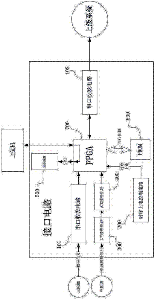
[0019] like figure 1 As shown, the interface circuit of a fiber optic gyro combination of the present invention is a small-volume signal acquisition and processing system as a whole, including:

[0020] Field Programmable Gate Array 700, referred to as FPGA;

[0021] The first serial port transceiver circuit 101, its input end is connected with three independent fiber optic gyros, and the output end is connected with the described FPGA700; The first serial port transceiver circuit 101 is used to receive the RS422 digital signal of three independent fiber optic gyroscopes, and output the optical fiber The gyroscope combines external navigation data.

[0022] Sequential power-on control circuit 200, which is connected to the FPGA700, is used to supply power to the three core voltages 1.0V, 2.5V and 3.3V, such as ...


PUM


Abstract

The invention discloses an interface circuit of a fiber-optic gyroscope combination. The interface circuit comprises an FPGA(Field Programmable Gate Array), a first serial transceiver circuit, a sequential electrifying control circuit, an I/V conversion amplifying circuit, a second serial transceiver circuit, and a PROM (Programmable Read-Only Memory). The FPGA is connected with an upper computer. An input end of the first serial transceiver circuit is connected with the fiber-optic gyroscope combination, and an output end of the first serial transceiver circuit is connected with the FPGA. The sequential electrifying control circuit is connected with the FPGA and used for charging the FPGA in a time sharing way. An input end of the I/V conversion amplifying circuit is connected with a meter combination while an output end thereof is connected with an input end of an A/D conversion circuit. An output end of the A/D conversion circuit is connected with the FPGA. One end of the second serial transceiver circuit is connected with the FPGA while the other end thereof is connected with a superior system. The second serial transceiver circuit is used for receiving information, about angular velocity and acceleration of the fiber-optic gyroscope combination and the meter combination, output from the FPGA, and then outputting the information to the superior system. The PROM is used for saving non-volatile soft programs for signal processing. The interface circuit has the advantages of simple structure and quick start of electrifying.

Description

technical field [0001] The invention relates to the field of inertial sensor measuring mechanism, in particular to an interface circuit for fiber optic gyroscope combination. Background technique [0002] In order to adapt to the development of spaceflight, the current weapon field is increasingly developing toward smaller size, longer range, and higher precision. Therefore, higher requirements are put forward for sensitive measurement mechanisms, and further requirements are smaller and better. Then The fiber optic gyro combination used in this field must have the characteristics of small size and fast power-on start-up. [0003] For the fiber optic gyroscope combination, the commonly used interface circuit has the following two disadvantages: [0004] One is that the volume is too large. The current input signal processing method is conventionally realized by an IF circuit. Although the circuit has high precision, its volume is relatively large, which cannot meet the smal...

Claims


Application Information

Patent Timeline
Patent Type & Authority Applications(China)
IPC IPC(8): G01C25/00
CPCG01C25/005
Inventor 肖波薛劲松吴成智贾瑞鹏邵添羿
Owner SHANGHAI AEROSPACE CONTROL TECH INST
Why Eureka
Try Eureka