
Image processing method and electronic equipment

A technology in images and images, applied in the field of data processing, can solve problems such as halo, and achieve the effect of avoiding the halo phenomenon

Active Publication Date: 2017-07-25
LENOVO (BEIJING) LTD
View PDF3 Cites 13 Cited by
  • Summary
  • Abstract
  • Description
  • Claims
  • Application Information

AI Technical Summary

Problems solved by technology

[0005] In view of this, the purpose of this application is to provide an image processing method and electronic equipment to solve the technical problem that the local tone mapping algorithm in the prior art will appear halo phenomenon on the image

Method used


Image

  • Image processing method and electronic equipment
  • Image processing method and electronic equipment
  • Image processing method and electronic equipment

Examples


Embodiment Construction

[0042] The following will clearly and completely describe the technical solutions in the embodiments of the application with reference to the drawings in the embodiments of the application. Apparently, the described embodiments are only some of the embodiments of the application, not all of them. Based on the embodiments in this application, all other embodiments obtained by persons of ordinary skill in the art without making creative efforts belong to the scope of protection of this application.

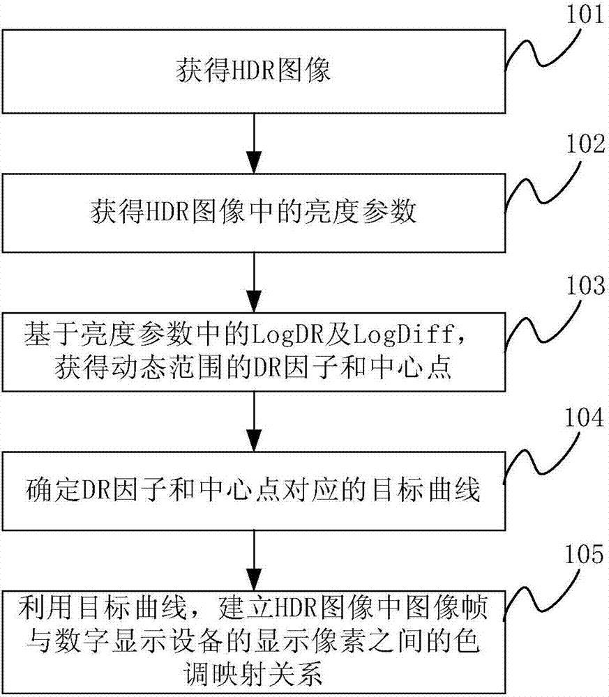
[0043] refer to figure 1 , is an implementation flowchart of an image processing method provided in Embodiment 1 of the present application, and is applicable to an application of mapping a high dynamic illumination rendering HDR image to an ordinary digital display device for display.

[0044] In this embodiment, the method may include the following steps:

[0045] Step 101: Obtain an HDR image.

[0046] Among them, the HDR image can be reconstructed by synthesizing a group of co...


PUM


Abstract

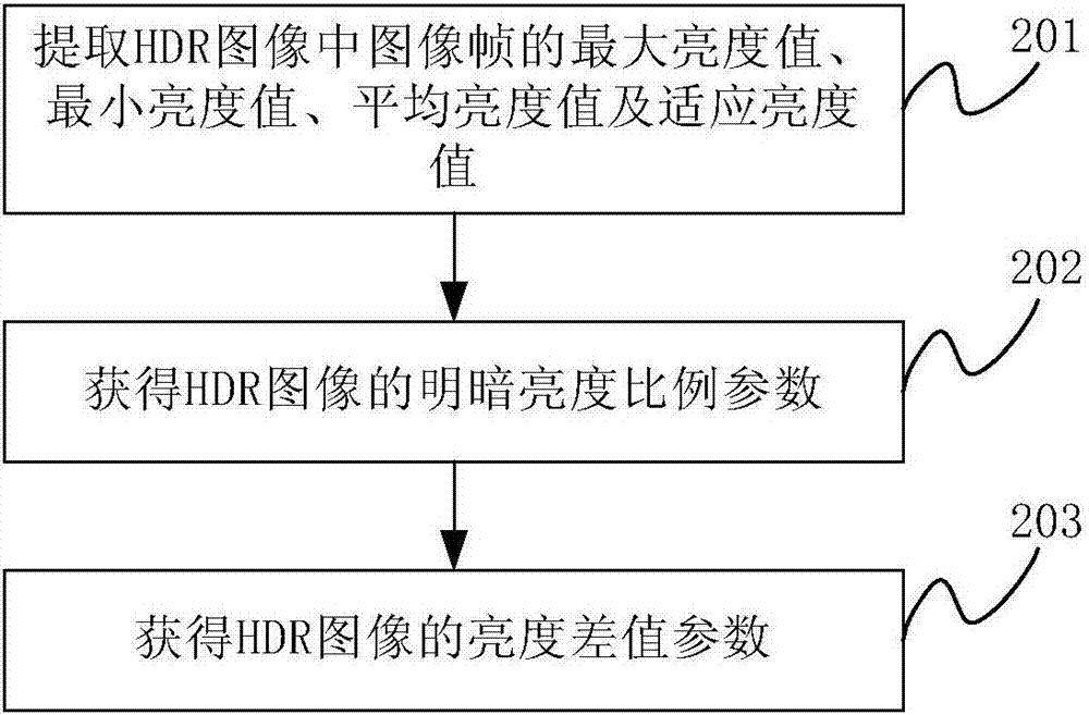
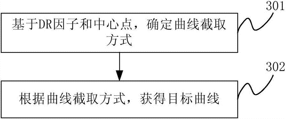
The invention discloses an image processing method and electronic equipment. The method comprises that an HDR (High-Dynamic Range) image is obtained; a brightness parameter including a brightness-darkness proportion parameter and a brightness difference parameter in the HDR image is obtained; on the basis of the brightness parameter, a DR (Dynamic Range) factor and a DR central point are obtained; a target curve corresponding to the DR factor and central point is determined; and the target curve is utilized to establish a tone mapping relation between a picture frame in the HDR image and a display pixel of digital display equipment. A global tone mapping realization scheme is used for the HDR image, and compared with a local tone mapping scheme in the prior art, an unnatural halation phenomenon in a local position in the image is avoided.

Description

technical field [0001] The present application relates to the technical field of data processing, in particular to an image processing method and electronic equipment. Background technique [0002] High dynamic range imaging (High Dynamic Range Imaging, HDR imaging) is a technology commonly used in imaging, photography, computer graphics and other fields. Its goal is to accurately reproduce , Reproducing real-world scenes with a wide dynamic range (from direct sunlight to the darkest shadows) perceived by human vision. High dynamic range imaging generally includes two parts: 1. Capture, acquisition, and synthesis of high dynamic images or radiation patterns; 2. Mapping high dynamic images or radiation patterns to common display devices, namely tone-mapping. [0003] At present, in pursuit of maximizing the contrast between bright and dark parts of the image within a wide dynamic range, most of the research is focused on the improvement of local tone mapping algorithms, that...

Claims


Application Information

Patent Timeline
Patent Type & Authority Applications(China)
IPC IPC(8): G06T5/00
CPCG06T2207/20208G06T2207/10152G06T5/73
Inventor 李浩
Owner LENOVO (BEIJING) LTD
Learn More