Power supply charging circuit of synchronous step-down power converter
A power converter and charging circuit technology, applied in the direction of adjusting electric variables, converting DC power input to DC power output, instruments, etc., can solve the problems of limited charging time of power supply VBOOST and difficulties in synchronous step-down power converters, etc. Achieve the effects of increasing charging time, large duty cycle, and fast recovery speed
- Summary
- Abstract
- Description
- Claims
- Application Information
AI Technical Summary
Problems solved by technology
Method used
Image

Examples
Embodiment 1
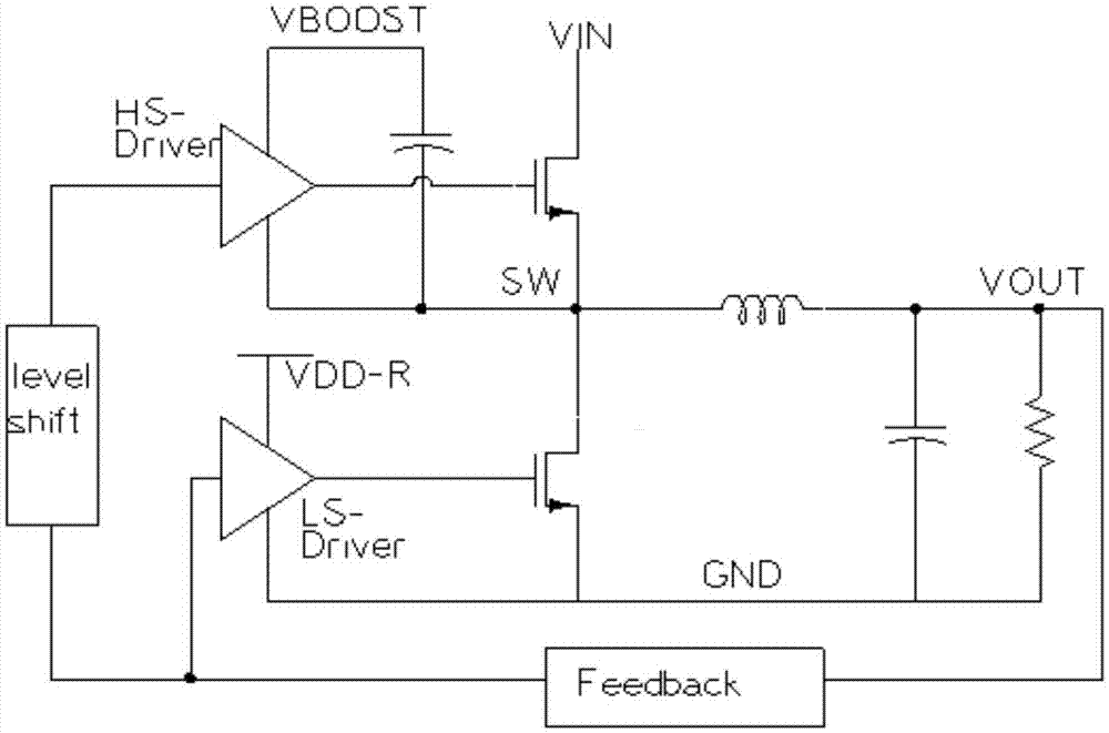
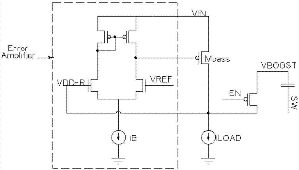
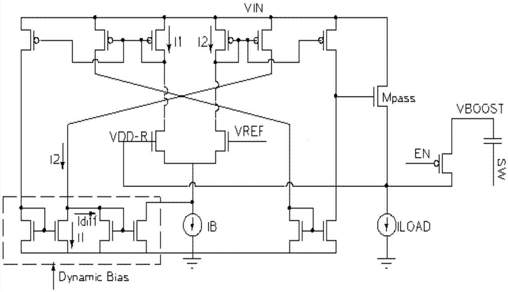
[0024] like image 3 As shown, this embodiment provides a power supply charging circuit for a synchronous step-down power converter, the synchronous step-down power converter includes a power supply VBOOST of an upper tube drive circuit, and the power charging circuit includes an error amplifier and an adjustment Tube Mpass, the error amplifier is used to generate an error voltage to adjust the adjustment tube so that the value of the power supply VDD-R is close to the reference The value of the voltage VREF is used to charge the power supply VBOOST by the power supply VDD-R. In addition, the power supply charging circuit also includes a dynamic bias module (Dynamic Bias).
[0025] The error amplifier is also used to generate a first current based on the power supply VDD-R, generate a second current based on the reference voltage VREF, and transmit the first current and the second current to the dynamic bias module;
[0026] The dynamic bias module is used for dynamically amp...
Embodiment 2
[0032] image 3 The circuit shown is the same as Figure 4 The combination of the shown circuit further improves the ability of the power supply VDD-R to charge the power supply VBOOST of the upper tube drive circuit.
[0033] Figure 4A VDD-R control circuit with push-pull capability is shown, which includes two first and second current amplifiers GML and GMH whose bias currents are controlled, a second pass transistor Mpass that flows through a large current, and 3 current mirrors (respectively a first current mirror, a second current mirror and a third current mirror). Wherein, the first current mirror, the second current mirror and the third current mirror are transistors M1 and M2, transistors M3 and M4, and transistors M5 and M6, respectively.
[0034] When the down tube is turned on and the power supply VDD-R is lower than the reference voltage VREF, the first current amplifier is used to receive a control signal to enable, generate a first current much larger than t...
PUM
 Abstract
Description
Claims
Application Information
 - R&D
- Intellectual Property
- Life Sciences
- Materials
- Tech Scout
- Unparalleled Data Quality
- Higher Quality Content
- 60% Fewer Hallucinations
Browse by: Latest US Patents, China's latest patents, Technical Efficacy Thesaurus, Application Domain, Technology Topic, Popular Technical Reports.
© 2025 PatSnap. All rights reserved.Legal|Privacy policy|Modern Slavery Act Transparency Statement|Sitemap|About US| Contact US: help@patsnap.com