Supercharge Your Innovation With Domain-Expert AI Agents!

A workbench for leather shoe pattern design

A workbench and shoe-like technology, which is applied in applications, home appliances, and legs of general furniture, etc., can solve the problems that the workbench cannot place flat plates or design tools, and it is inconvenient for designers to design work.

Active Publication Date: 2020-07-17
台州西西龙体育用品有限公司
View PDF13 Cites 1 Cited by
  • Summary
  • Abstract
  • Description
  • Claims
  • Application Information

AI Technical Summary

Problems solved by technology

[0007] In order to overcome the shortcomings in the prior art that the current workbench cannot place flat plates or design tools, which is inconvenient for designers to design, the technical problem to be solved by the present invention is to provide a shoe-like design that has the function of placing and is easy to use use a workbench

Method used


Image

  • A workbench for leather shoe pattern design
  • A workbench for leather shoe pattern design
  • A workbench for leather shoe pattern design

Examples


Embodiment 1

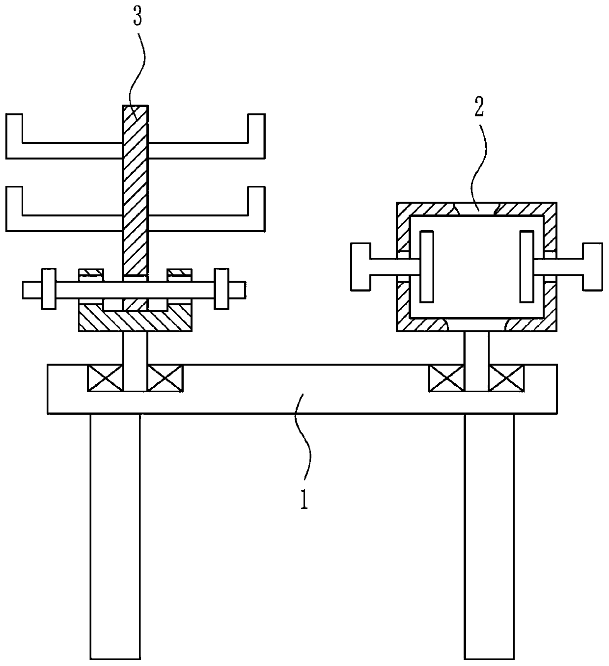
[0038] A workbench for shoe pattern design, such as Figure 1-7 As shown, a workbench 1, a first placement mechanism 2 and a second placement mechanism 3 are included, the first placement mechanism 2 is provided on the right side of the top of the workbench 1, and the second placement mechanism 3 is provided on the left side of the top of the workbench 1.

Embodiment 2

[0040] A workbench for shoe pattern design, such as Figure 1-7 As shown, a workbench 1, a first placement mechanism 2 and a second placement mechanism 3 are included, the first placement mechanism 2 is provided on the right side of the top of the workbench 1, and the second placement mechanism 3 is provided on the left side of the top of the workbench 1.

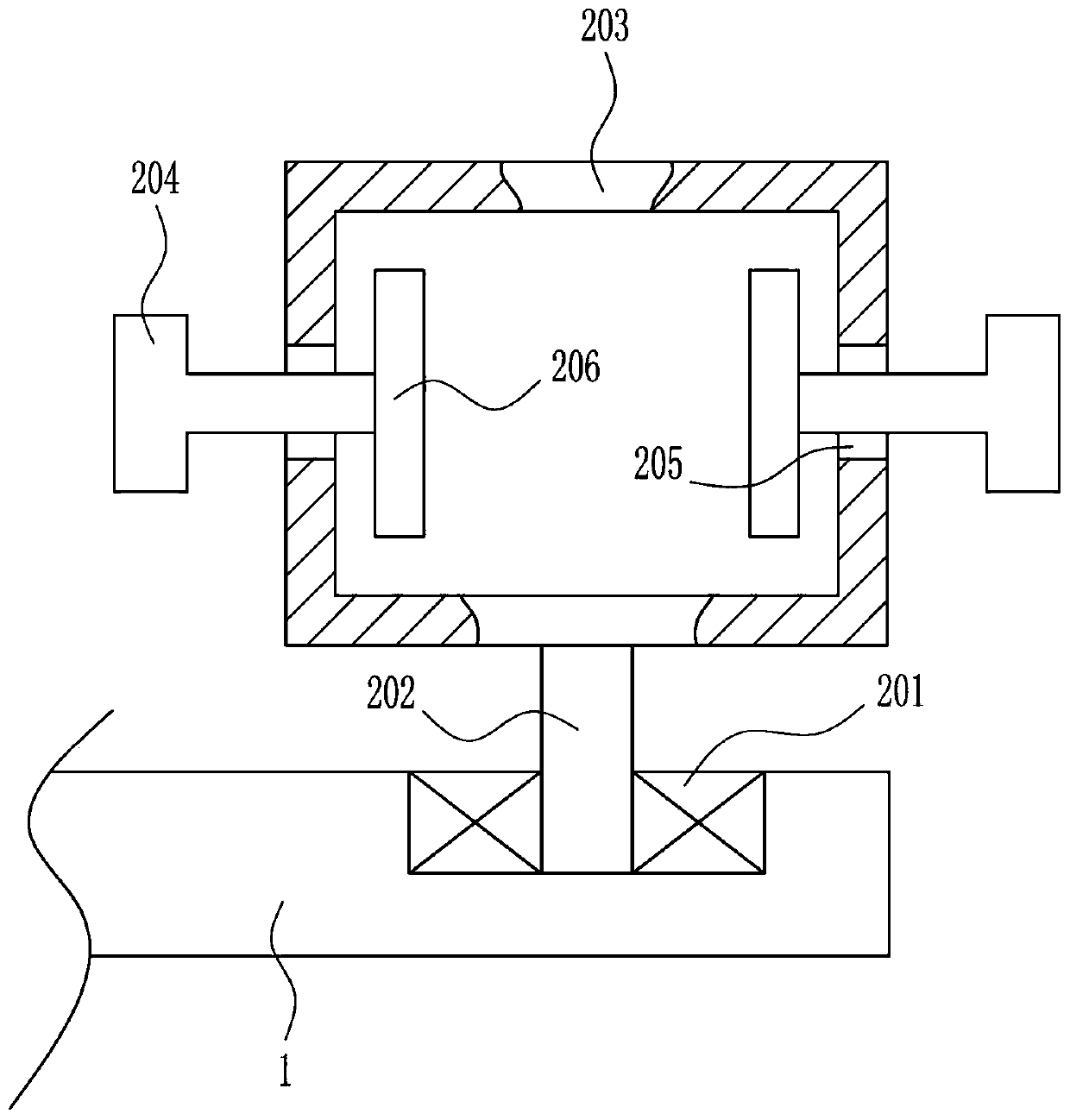
[0041] The first placement mechanism 2 includes a first bearing seat 201, a first rotating rod 202, a placement frame 203, a pole 204 and a rubber block 206. The right side of the top of the workbench 1 is provided with a first bearing seat 201, and the first bearing seat 201 The inner bearing is connected with a first rotating rod 202, the top of the first rotating rod 202 is connected with a placement frame 203, the left and right walls of the placement frame 203 are provided with threaded holes 205, the left and right walls of the placement frame 203 are provided with poles 204, and the poles 204 There are threads on it,...

Embodiment 3

[0043] A workbench for shoe pattern design, such as Figure 1-7 As shown, a workbench 1, a first placement mechanism 2 and a second placement mechanism 3 are included, the first placement mechanism 2 is provided on the right side of the top of the workbench 1, and the second placement mechanism 3 is provided on the left side of the top of the workbench 1.

[0044] The first placement mechanism 2 includes a first bearing seat 201, a first rotating rod 202, a placement frame 203, a pole 204 and a rubber block 206. The right side of the top of the workbench 1 is provided with a first bearing seat 201, and the first bearing seat 201 The inner bearing is connected with a first rotating rod 202, the top of the first rotating rod 202 is connected with a placement frame 203, the left and right walls of the placement frame 203 are provided with threaded holes 205, the left and right walls of the placement frame 203 are provided with poles 204, and the poles 204 There are threads on it,...


PUM


Abstract

The invention relates to a working table, in particular to a working table for designing leather-shoe patterns. The invention aims to achieve the technical purpose that a working table which has a placing function and is convenient to use for leather-shoe pattern designing is provided. In order to achieve the technical purpose, the working table for designing the leather-shoe patterns comprises a working table body, a first placing mechanism, a second placing mechanism and the like, wherein the first placing mechanism is disposed on the top right of the working table body, and the second placing mechanism is mounted on the top left of the working table body. The working table for designing the leather-shoe patterns enables a designer to use a tablet PC conveniently through disposition of the first placing mechanism, and meanwhile is provided with the second placing mechanism.

Description

technical field [0001] The invention relates to a workbench, in particular to a workbench for designing leather shoes. Background technique [0002] Leather shoes are footwear with natural leather as the upper and leather or rubber, plastic, PU foam, PVC, etc. as the sole, which are processed by sewing, gluing or injection molding. Leather shoes are air-permeable, moisture-absorbing, have good hygienic performance, and are the shoes with the highest grade among all kinds of shoes and boots. [0003] Thousands of years ago, human ancestors had the habit of wearing shoes, wrapping their feet with animal skins, from leather shoes to modern leather shoes, leather shoes have a long history. In China, the production of modern leather shoes has only a history of more than 120 years, but because the shape, style, structure and wearing function of leather shoes are better than other footwear, the production of leather shoes has developed rapidly. Nowadays, leather shoes have become...

Claims


Application Information

Patent Timeline
Patent Type & Authority Patents(China)
IPC IPC(8): A47B37/00A47B13/00
CPCA47B13/00A47B37/00
Inventor 杨国祥
Owner 台州西西龙体育用品有限公司
Features
  • R&D
  • Intellectual Property
  • Life Sciences
  • Materials
  • Tech Scout
  • Unparalleled Data Quality
  • Higher Quality Content
  • 60% Fewer Hallucinations
Learn More