A multi-wave hydraulic automatic forming method for small-diameter metal bellows

A metal bellows and automatic forming technology is applied in the field of multi-wave hydraulic automatic forming of small-diameter metal bellows below 10mm, which can solve the problems of difficulty in multi-wave hydraulic automatic forming, no metal bellows being produced, and bellows being scrapped. Achieve the effect of low cost, high value, and improved processing efficiency

Active Publication Date: 2018-12-07
HEFEI JIANGHANG AIRCRAFT EQUIP CORP LTD
View PDF7 Cites 0 Cited by
  • Summary
  • Abstract
  • Description
  • Claims
  • Application Information

AI Technical Summary

Problems solved by technology

[0002] At present, the processing of metal bellows with a diameter of more than 10mm can realize hydraulic automatic forming, but it is difficult to realize the multi-wave hydraulic automatic forming of small-diameter metal bellows with a diameter of less than 10mm, because the original processing method for large diameters is used in small diameter metal bellows, causing the bellows to be scrapped, and no qualified metal bellows can be produced, so further exploration is needed

Method used


Image

  • A multi-wave hydraulic automatic forming method for small-diameter metal bellows
  • A multi-wave hydraulic automatic forming method for small-diameter metal bellows

Examples


Embodiment 1

[0015] Embodiment 1: processing a bellows with a diameter of 10mm, the steps are as follows:

[0016] Step 1: Determine the mold cavity clearance, which is 0.20-0.22mm;

[0017] Step 2: Determine the diameter of the hydraulic inlet fixture, which is 3.5-4.0mm;

[0018] Step 3: Fitter assembly, so that the template of the mold is in a horizontal state;

[0019] Step 4: Select No. 68 anti-wear hydraulic oil;

[0020] Step 5: Insert the tube blank into the inlet fixture, adjust the total pressure on the hydraulic press to 13MPa, close the mold, pressurize the tube blank, push the bottom of the tube blank to move towards the inlet fixture, make the templates between the molds contact, and then unload Press, pull open the mold, and take out the formed product bellows.

Embodiment 2

[0021] Embodiment 2: processing a bellows with a diameter of 8mm, the steps are as follows:

[0022] Step 1: Determine the mold cavity clearance, which is 0.22-0.25mm;

[0023] Step 2: Determine the diameter of the hydraulic inlet fixture, which is 3.0mm;

[0024] Step 3: Fitter assembly, so that the template of the mold is in a horizontal state;

[0025] Step 4: Select No. 68 anti-wear hydraulic oil;

[0026] Step 5: Insert the tube blank into the inlet fixture, adjust the total pressure on the hydraulic press to 13MPa, close the mold, pressurize the tube blank, push the bottom of the tube blank to move towards the inlet fixture, make the templates between the molds contact, and then unload Press, pull open the mold, and take out the formed product bellows.

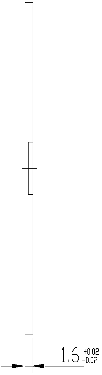
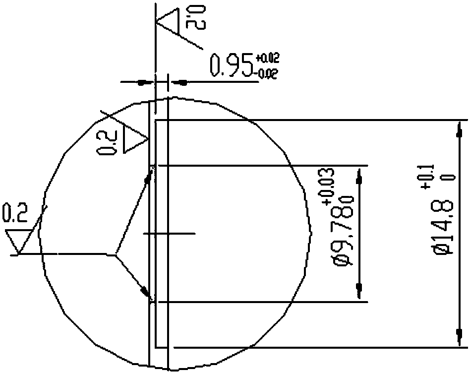
[0027] The schematic diagram of the mold template in the processing of bellows with a diameter of 8mm is as follows figure 1 , 2 As shown, the relevant dimensions are: the thickness of the template is 1.6mm, the tol...


PUM

PropertyMeasurementUnit
sizeaaaaaaaaaa
sizeaaaaaaaaaa
diameteraaaaaaaaaa

Abstract

The invention relates to a multi-wave hydraulic automatic molding method for a metal corrugated pipe with diameter smaller than or equal to 10 mm. The multi-wave hydraulic automatic molding method includes the following steps that (1) the mold cavity gap is determined to be 0.2 mm to 0.25 mm; (2) the drift diameter of a hydraulic inlet clamp is determined to be 3 mm to 4 mm; (3) bench worker assembling is carried out to enable mold plates of molds to be in the horizontal state; (4) No.68 wear-resistant hydraulic oil is selected and matched; and (5) a tube blank is inserted into the inlet clamp to enable the mold to achieve mold assembly, the tube blank is inflated with pressure, the bottom of the tube blank is pushed to move to the inlet clamp, the mold plates between the molds are in contact, then pressure releasing is carried out, the molds are pulled to be open, and the molded corrugated pipe is taken out. According to the multi-wave hydraulic automatic molding method, the problem that multi-wave hydraulic automatic molding of the metal corrugated pipe with diameter smaller than or equal to 10 mm cannot be achieved through the existing method is solved, and the problems in production and manufacturing are solved.

Description

technical field [0001] The invention belongs to the application field of liquid hydraulic forming, and relates to a multi-wave hydraulic automatic forming method for metal bellows with a diameter of less than 10 mm. Background technique [0002] At present, the processing of metal bellows with a diameter of more than 10mm can realize hydraulic automatic forming, but it is difficult to realize the multi-wave hydraulic automatic forming of small-diameter metal bellows with a diameter of less than 10mm, because the original processing method for large diameters is used in small Diameter metal bellows, resulting in the scrapping of the bellows, no qualified metal bellows can be produced, so further exploration is needed. Contents of the invention [0003] Aiming at the existing problems such as difficulty in realizing multi-wave hydraulic automatic forming of metal bellows with a diameter below Φ10mm and low yield rate, the present invention provides a forming method capable o...

Claims


Application Information

Patent Timeline
Patent Type & Authority Patents(China)
IPC IPC(8): B21D15/10
CPCB21D15/10
Inventor 石伟林
Owner HEFEI JIANGHANG AIRCRAFT EQUIP CORP LTD
Why Eureka
Try Eureka