Clamping device for workpiece air tightness inspection

An air-tightness inspection and clamping device technology, applied in workpiece clamping devices, liquid/vacuum measurement for liquid-tightness, manufacturing tools, etc. and other problems, to achieve the effect of solving sealing difficulties, safe and reliable clamping, and high work efficiency

Active Publication Date: 2018-08-31
常州市盛士达汽车空调有限公司
View PDF7 Cites 0 Cited by
  • Summary
  • Abstract
  • Description
  • Claims
  • Application Information

AI Technical Summary

Problems solved by technology

[0003] When the tooling is operated horizontally, the claws are relatively loose in the reset state, and the opening end of the upper claws sags due to the action of gravity, making it difficult to insert the rubber hose; The bottom is compactly arranged, and the top has a large gap. When shrinking, the phenomenon of "clamping meat" will occur, which will easily damage the rubber hose and fail to achieve the purpose of sealing. Moreover, the device is reset by a spring, and the force of the spring is difficult to overcome the friction force and is easy to get stuck. , Need to pull the rubber hose to assist reset, high labor intensity and low work efficiency

Method used


Image

  • Clamping device for workpiece air tightness inspection
  • Clamping device for workpiece air tightness inspection
  • Clamping device for workpiece air tightness inspection

Examples


Embodiment Construction

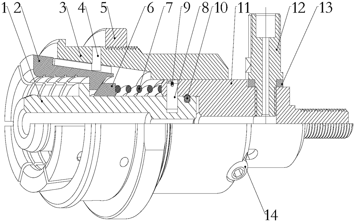
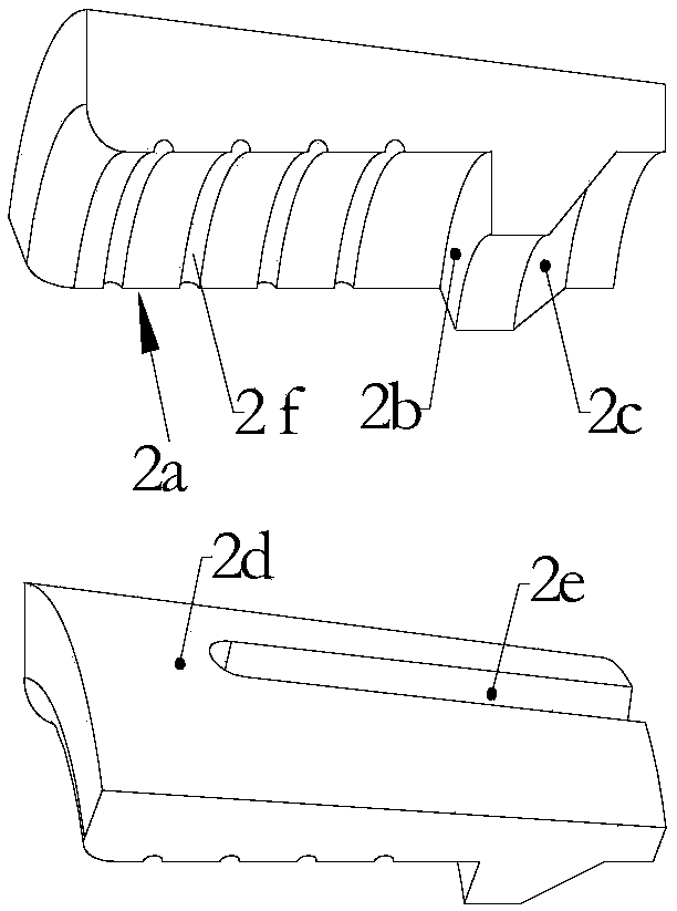
[0032] The clamping device for workpiece air tightness inspection of the present invention comprises: a hollow shaft 1, a sliding rod 11, a clamping mechanism 2, a sliding sleeve 6, a compression reset part 7, a pressing sleeve 3, and a driving mechanism, and the bottom faces between them. The relationship is described in detail:

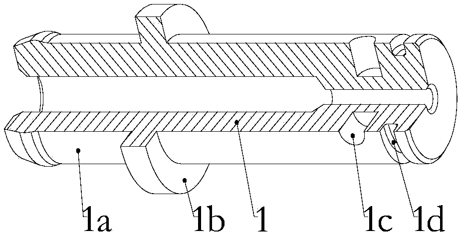
[0033] Such as figure 1 and figure 2 As shown, the outer peripheral surface 1a of one end of the hollow shaft 1 is provided with a first limiting portion 1b, and the first limiting portion 1b is an annular protrusion; the outer peripheral surface of the other end of the hollow shaft 1 is provided with an assembly hole 1c and the first annular groove 1d, the sealing ring 10 is installed in the first annular groove 1d.

[0034] One end of the sliding rod 11 is provided with a ventilation hole, and after the end of the sliding rod 11 provided with the ventilation hole is fixedly connected with the hollow shaft 1, the ventilation hole on the sliding...


PUM


Abstract

The invention relates to a clamping device for workpiece airtightness testing. The clamping device comprises a hollow shaft, a sliding rod, a clamping mechanism, a pressing sleeve, a sliding sleeve and a compression restoration part. A first limiting part is arranged on the outer circumferential surface of one end of the hollow shaft. A ventilating hole is formed in one end of the sliding rod. The clamping mechanism surrounds the hollow shaft. A spaced space is formed between the clamping mechanism and the hollow shaft in the radial direction. A radial protrusion is arranged on the inner wall surface of the clamping mechanism. A tapered surface is arranged at the end, departing from the first limiting mechanism, of the radial protrusion. At least one part of an inner hole of the pressing sleeve is a tapered hole. The outer circumferential surface of the clamping mechanism is a tapered surface. One end of the pressing sleeve is sleeved with the clamping mechanism, and the tapper surface of the pressing sleeve is matched with the tapered surface of the clamping mechanism. The hollow shaft is sleeved with the sliding sleeve, and the radial protrusion is clamped between the first limiting part and the sliding sleeve. One end of the compression restoration part abuts against the sliding sleeve or is connected with the sliding sleeve, and the other end of the compression restoration part abuts against a sliding rod or is connected with the sliding rod. The clamping device for workpiece airtightness testing has the advantage that clamping is easy.

Description

technical field [0001] The invention relates to a pipeline airtightness inspection, in particular to a clamping device for workpiece airtightness inspection. Background technique [0002] With the continuous increase of automobile production, the demand for rubber hoses used in automobiles is also increasing. Due to the increasingly fierce competition in the industry, various companies are doing lean production to maximize their profits. In summary, in order to improve production efficiency and reduce costs, it has become a general trend. After the rubber hose product is formed, it needs to be inspected for air tightness. Currently, the tooling used is such as Figure 7 As shown, it includes a core body 1, a claw 2, a sliding sleeve 3, a handle 4, a snap spring 5 and a joint 6, the claw 2 is distributed around one end of the core body 1, and one end of the sliding sleeve 3 is sleeved on the core body 1. The sliding sleeve 3 is provided with a first limiting part, and one en...

Claims


Application Information

Patent Timeline
Patent Type & Authority Patents(China)
IPC IPC(8): B25B11/00G01M3/02
CPCB25B11/00G01M3/02
Inventor 朱庆柱
Owner 常州市盛士达汽车空调有限公司
Why Eureka
Try Eureka