Electric linear vertical lifting device

A technology of vertical lifting and vertical lifting mechanism, applied in the field of electric linear vertical lifting device, can solve the problems of difficult to accurately capture the pupil center, human eye parameter error, visual fatigue, etc., to reduce visual fatigue, accurate capture, accurate capture. Effect

Pending Publication Date: 2017-07-28
TAIYUAN XINYUAN HIGH-TECH CENT NORTH UNIV OF CHINA
View PDF5 Cites 0 Cited by
  • Summary
  • Abstract
  • Description
  • Claims
  • Application Information

AI Technical Summary

Problems solved by technology

Because the refractor turns the handle by hand, it is not only laborious and time-consuming, but also causes visual fatigue for the patient, and it is difficult to accurately capture the pupil center of the human eye, which leads to large errors in the measured human eye parameters.

Method used


Image

  • Electric linear vertical lifting device
  • Electric linear vertical lifting device

Examples


Embodiment 1

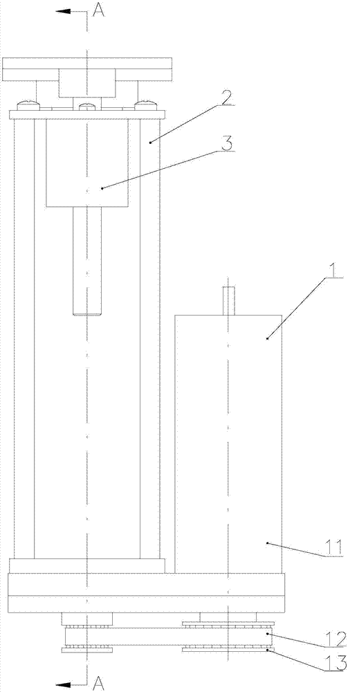
[0024] An electric linear vertical lifting device, comprising: a motor drive mechanism 1,

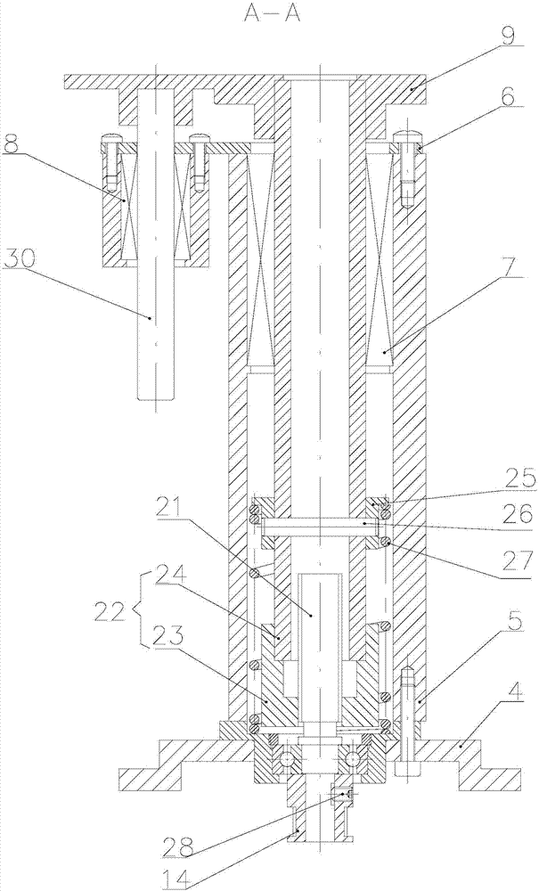
[0025] The linear vertical lifting mechanism 2 is drivingly connected with the motor drive mechanism 1, wherein the linear vertical lifting mechanism 2 includes a threaded rod 21 and a moving part 22 engaged with the screw rod 21 for driving the motor drive mechanism 1 Under the condition that the screw rod 21 moves, the vertical movement of the moving part 22 in the vertical direction is realized through the meshing effect of the screw rod 21 and the moving part 22;

[0026] The guide mechanism 3 is located at the front part of the linear vertical lifting mechanism 2 and is connected with it as a whole. When the moving part 22 moves in the vertical direction, the guide mechanism 3 is consistent with the linear vertical lifting mechanism 2 to realize the alignment. Rapid guidance of the optical measuring system in the vertical direction.

Embodiment 2

[0028] Such as figure 1 , 2 As shown, an electric linear vertical lifting device includes: a motor drive mechanism 1, a linear vertical lifting mechanism 2, a guiding mechanism 3, a support 4, a fixed cylinder 5, a limit plate 6, a first linear bearing 7, a second Linear bearing 8, top plate 9.

[0029] Both the motor drive mechanism 1 and the linear vertical lifting mechanism 2 are fixed on the support 4, and the two are connected by a conveyor belt transmission method, and the belt transmission connection method is preferably used in this example. The guiding mechanism 3 is located at the front part of the linear vertical lifting mechanism 2 and is integrally connected with it.

[0030] The structural form and motion process of each mechanism are introduced respectively below.

[0031] Described motor driving mechanism 1 comprises a driving motor 11, a conveyor belt 12, a large synchronous wheel 13 and a small synchronous wheel 14, and the described driving motor 11 is fi...


PUM


Abstract

The invention relates to an electric linear vertical lifting device which comprises a motor driving mechanism, a linear vertical lifting mechanism and a guide mechanism, wherein the linear vertical lifting mechanism is in drive joint with the motor driving mechanism and comprises a screw rod and a moving part meshed with the screw rod; and the guide mechanism is positioned in front of the linear vertical lifting mechanism and the guide mechanism and the linear vertical lifting mechanism are integrally connected. According to the invention, through the synergistic effect of a conveyer belt and a synchronizing wheel, the motor driving mechanism drives the screw rod of the linear vertical lifting mechanism to rotate, so that a moving shaft of the linear vertical lifting mechanism is enabled to do lifting motion in the direction perpendicular to the y-axis; and in addition, the guide mechanism and the linear vertical lifting mechanism are integrally and fixedly connected to realize vertical lifting motion of the guide mechanism and an optical measurement system, so that the speed that a full-automatic computer optometry apparatus captures the interpupillary distance center of a human eye is increased, time and labor are saved, and the defect that an optometrist rotates a handle by hand to enable the optical measurement system to vertically go up and down is overcome.

Description

technical field [0001] The invention relates to a lifting device, in particular to an electric linear vertical lifting device, in particular to an electric linear vertical lifting device used in a fully automatic computer optometry instrument. Background technique [0002] When measuring the parameters of the patient's human eye, the refractor requires fast and accurate capture of the human eye. At present, during the optometry process of the optometry instrument, the optometrist usually rotates the handle in the vertical y direction, and the optical test system of the instrument is driven vertically up and down in the y direction by the belt to capture the human eye. Because the refractor turns the handle by hand, it is not only laborious and time-consuming, but also causes visual fatigue for the patient in the measurement, and it is difficult to accurately capture the pupil center of the human eye, which leads to large errors in the measured human eye parameters. Content...

Claims


Application Information

Patent Timeline
Patent Type & Authority Applications(China)
IPC IPC(8): F16H37/12H02K7/10A61B3/00A61B3/11
CPCA61B3/0075A61B3/111H02K7/1004F16H37/124
Inventor 杜晓军赵俊奇阎洁刘俊贤黄鑫云
Owner TAIYUAN XINYUAN HIGH-TECH CENT NORTH UNIV OF CHINA
Why Eureka
Try Eureka