
Measuring device and method for structural clearance of non-visible parts of stitching antenna

A technology for antenna measurement and measurement devices, which is applied in the direction of measurement devices, optical devices, instruments, etc., can solve problems such as the inability to obtain the antenna gap value, the inability to use it, and the inability to realize accurate measurement of millimeter-level tiny gaps, so as to reduce the risk of deployment, Ensure smooth deployment and avoid interference

Active Publication Date: 2019-05-28
SHANGHAI AEROSPACE SYST ENG INST
View PDF5 Cites 0 Cited by
  • Summary
  • Abstract
  • Description
  • Claims
  • Application Information

AI Technical Summary

Problems solved by technology

For example, the patent application "A Method for Measuring the Gap of Pinch Roller Bearings" (CN200910053498.7), and the patent application "A Gap Measurement Tool and Gap Qualified Measurement Method" (CN201510013064.X), related methods for gap measurement described, however, the distance measurement methods in these patent applications cannot be used to measure where internal clearances are relatively small
The patent application "Internal Gap Measuring Device" (CN201220325127.7) designed an internal gap measuring device, which obtains the gap value by directly placing a sensor with a pressure sensing head and a spring plate in the measured gap, but the internal gap Due to the limitation of the size of the measuring head, the measuring device is only suitable for larger gaps, and cannot accurately measure millimeter-level small gaps; and the internal gap measuring device can only measure when the antenna is fully deployed and in place, and cannot be used when the antenna is fully extended. Obtain the gap value after antenna deployment in advance before deployment

Method used


Image

  • Measuring device and method for structural clearance of non-visible parts of stitching antenna
  • Measuring device and method for structural clearance of non-visible parts of stitching antenna
  • Measuring device and method for structural clearance of non-visible parts of stitching antenna

Examples


Embodiment Construction

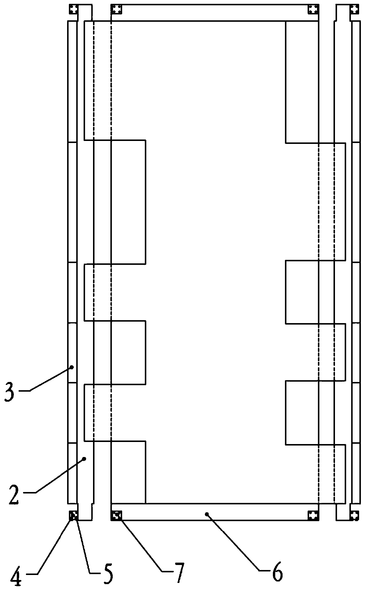
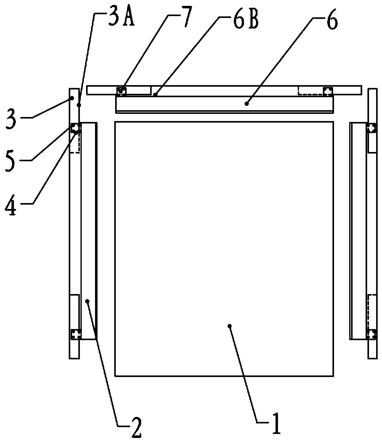
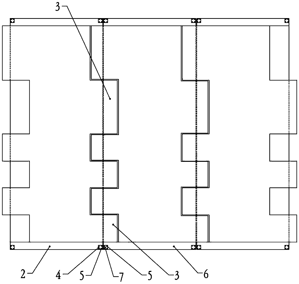
[0031] The following will combine Figure 1 to Figure 7 A further detailed description will be made on the device and method for measuring the structure gap of the non-visible part of the spliced ​​antenna of the present invention.

[0032] figure 1 Shown is the front view of the folded state of the space-borne large-scale antenna in the preferred embodiment of the present invention; figure 2 Shown is the top view of the folded state of the space-borne large-scale antenna in the preferred embodiment of the present invention; image 3 Shown is the front view of the state in which the satellite-borne large-scale antenna is deployed in place in a preferred embodiment of the present invention; Figure 4 Shown is the top view of the space-borne large-scale antenna deployed in place in the preferred embodiment of the present invention.

[0033] Such as Figure 1 to Figure 4 As shown, the space-borne large-scale antenna of this embodiment adopts a dislocation splicing method. Th...


PUM


Abstract

The invention provides a splicing antenna non-visible part structure gap measuring device and method. An antenna side plate framework is provided with side plate antenna measurement references. An antenna middle plate framework is provided with middle plate antenna measurement references. The side plate antenna measurement references and the middle plate antenna measurement references are bonded with a measurement target respectively. A measurement instrument is arranged just in front of a satellite body for measuring the measurement targets. The fixation relation between the references and the measurement surface is utilized to covert the gap of the non-visible part onto the reference surface, and the conventional testing means is utilized for gap measurement. Meanwhile, through the three-dimensional orthogonal design of the references and 90 DEG expansion association of the antenna, the object of predicting the gap after the antenna is expanded to a preset position is achieved through measuring the orthogonal reference surface of a tested surface in a folded state.

Description

technical field [0001] The invention relates to detection and measurement technology, in particular to a device and method for measuring structural gaps at non-visible parts of spliced ​​antennas. Background technique [0002] Limited by the space size of the launch vehicle, large space-borne antennas are generally folded and folded on the side wall of the satellite during launch, and unfolded in orbit after entering orbit. For example, a large space-borne antenna adopts a dislocation splicing method. According to the electrical performance requirements of the antenna, the gap at the joint of the spaceborne large-scale antenna is small (millimeter level). Considering the manufacturing and assembly accuracy, if the gap detection is not properly controlled, the deployment process will cause structural interference and damage the antenna. In order to ensure the smooth deployment of the antenna in orbit, it should be ensured that there is no structural interference and collision...

Claims


Application Information

Patent Timeline
Patent Type & Authority Patents(China)
IPC IPC(8): G01B11/14
CPCG01B11/14
Inventor 陈晓峰刘子仙钟鸣邢健程庆清梁宝柱张利平周鑫
Owner SHANGHAI AEROSPACE SYST ENG INST
Learn More