Sensor positioning device for explosive loading response stress tests

A technology of stress testing and positioning devices, which is applied in the direction of measuring devices, instruments, scientific instruments, etc., can solve the problems of dumping of drop-weight bombs, failure to reuse, and reduced stability of drop-weight bombs, so as to prevent accidental dumping and facilitate The effect of taking out and reusing

Active Publication Date: 2017-07-28
XIAN MODERN CHEM RES INST
View PDF4 Cites 12 Cited by
  • Summary
  • Abstract
  • Description
  • Claims
  • Application Information

AI Technical Summary

Problems solved by technology

The main problem is that the steel sensor will expand radially under the action of impact, and then tightly bond with the inner wall of the sleeve, making it difficult to remove the sensor completely and cannot be reused
Wang Shiying and others disclosed the stress of an explosive charge under the impact of a falling hammer in the article "Research on the Stress Test Method of Explosive Charges Under the Impact of Dropping Hammers" (2013 Mechanics Measurement Technology Academic Symposium Papers Collection). Response test method, in which the sensor is still connected to the force transmission column, but the sensor is placed outside the sleeve, which avoids the problem that the radial expansion of the steel sensor is difficult to take out, but at the same time introduces a new problem: during the impact loading process, the sensor and The force transmission column in the sleeve cannot accurately maintain the coaxiality, and the stability of the entire drop weight sample bomb is reduced during the impact process, and the drop weight sample bomb may even fall over, which will affect the test results

Method used


Image

  • Sensor positioning device for explosive loading response stress tests
  • Sensor positioning device for explosive loading response stress tests
  • Sensor positioning device for explosive loading response stress tests

Examples


Embodiment Construction

[0015] Below in conjunction with accompanying drawing and embodiment the present invention is described in further detail, it should be noted that the present invention is not limited to following specific embodiment, all equivalent transformations carried out on the basis of the technical solution of the present invention are all within the scope of protection of the present invention.

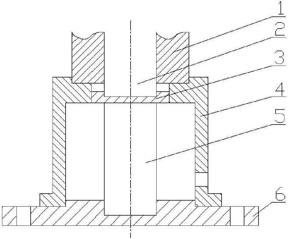
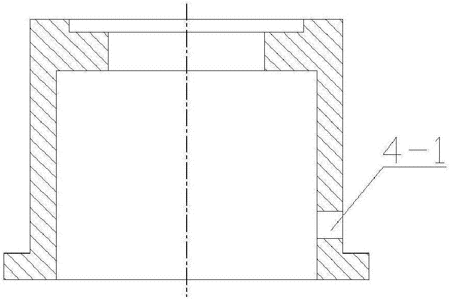
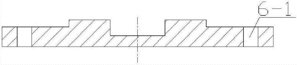
[0016] Comply with the above technical solutions, such as Figure 1-Figure 4 As shown, this embodiment provides a sensor positioning device for explosive charge response stress testing, including a positioning bracket 4, a positioning piece 3, a backing plate 6, and is characterized in that it also includes a sleeve 1, a force transmission column 2 and a sensor 5, Wherein, the positioning bracket 4 is a variable-diameter steel cylinder with a boss inside, and the ratio of the outer diameter of the positioning bracket 4 to the outer diameter of the sleeve 1 is about 1.3 to 1.5:1. In this embodi...


PUM

PropertyMeasurementUnit
diameteraaaaaaaaaa
heightaaaaaaaaaa

Abstract

The invention discloses a sensor positioning device for explosive loading response stress tests. The sensor positioning device comprises a positioning support, a positioning piece, a base plate, a sleeve, a force transfer column and a sensor. The positioning support is a variable-diameter steel cylinder with an inner boss. One end of the positioning support is connected with the sleeve, and the force transfer column is mounted in the sleeve. The other end of the positioning support is connected with the base plate, and is positioned by a center boss on the base plate. The positioning piece is mounted at the inner boss of the positioning support. One end of the positioning piece is connected with the force transfer column, and the other end of the positioning piece contacts with the sensor tightly. The other end of the sensor is mounted in a round groove of the base plate. The sensor positioning device for the explosive loading response stress tests has the advantages that the sensor can be conveniently taken out and recycled after being impacted and loaded, the sensor can keep a good coaxial line with the force transfer column, accidental collapse of the sleeve during loading can be prevented, and technical support can be provided to convenient and accurate measurement of explosive loading response stress.

Description

technical field [0001] The invention belongs to the technical field of experimental devices for explosives laboratories, and relates to an object positioning device under the action of impact load, in particular to a sensor positioning device suitable for indirectly measuring the response stress of explosive charge under the action of impact load. Background technique [0002] Explosive charges are often subject to impact loads during launch and penetration. In these processes, the response of explosive charges is firstly a dynamic response, the most important of which is the response stress of explosive charges, which may affect its safety performance. The development of modern high-performance weapon systems has put forward higher requirements for the safety of explosive charges under shock loads, and the dynamic response of explosive charges under shock loads has also received more and more attention. Therefore, how to realize the safety of explosive charges The convenie...

Claims


Application Information

Patent Timeline
Patent Type & Authority Applications(China)
IPC IPC(8): G01N3/02G01N3/313
CPCG01N3/02G01N3/313G01N2203/001
Inventor 屈可朋李亮亮沈飞王辉肖玮
Owner XIAN MODERN CHEM RES INST
Why Eureka
Try Eureka