Optical imaging system

An optical imaging system, imaging surface technology, applied in optics, optical components, instruments, etc., can solve problems such as total length and general imaging quality

Active Publication Date: 2017-07-28
ZHEJIANG SUNNY OPTICAL CO LTD
View PDF3 Cites 25 Cited by
  • Summary
  • Abstract
  • Description
  • Claims
  • Application Information

AI Technical Summary

Problems solved by technology

[0003] At present, the general wide-angle lens is mainly made of all-glass structure, the total length is long, and the imaging quality is average; due to the increasing development of portable electronic products, especially the 360-degree surround view application that is currently increasing in the market, the miniaturization of the camera lens, Performances such as light weight, ultra-wide-angle and imaging quality put forward further higher requirements

Method used


Image

  • Optical imaging system
  • Optical imaging system
  • Optical imaging system

Examples


Embodiment 1

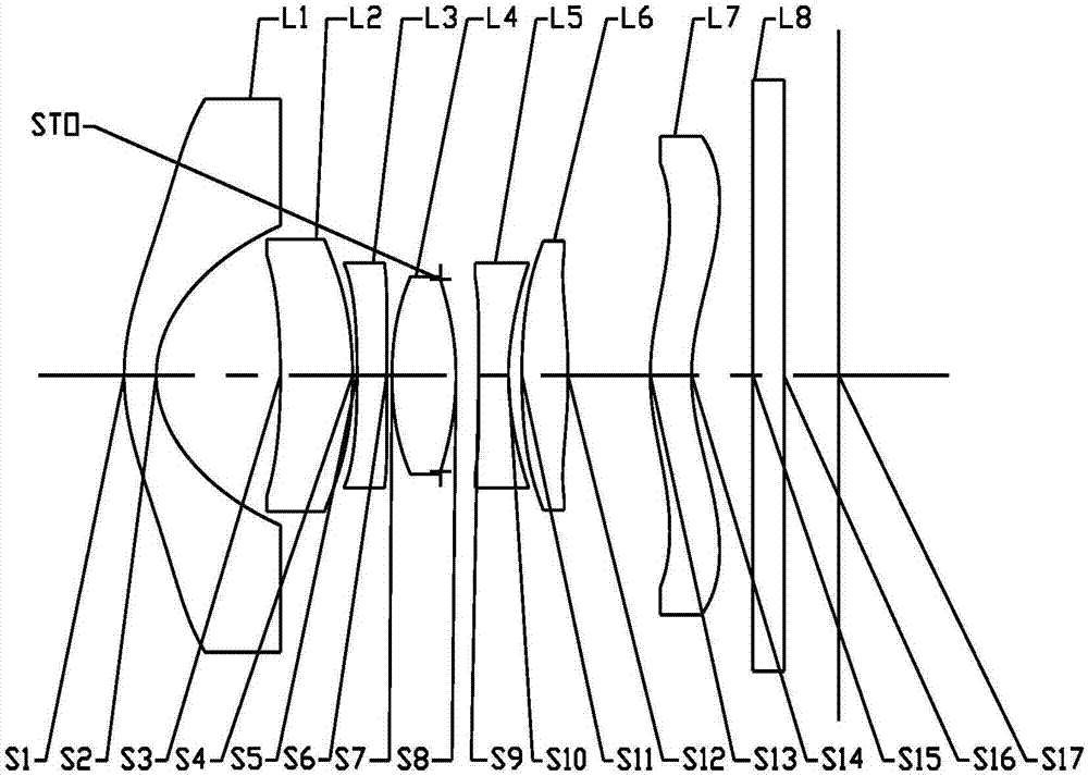
[0068] Refer to the following Figure 1 to Figure 2D An optical imaging system according to Embodiment 1 of the present application is described.

[0069] figure 1 A schematic structural diagram of an optical imaging system according to Embodiment 1 of the present application is shown. Such as figure 1 As shown, the optical imaging system includes seven lenses L1-L7 arranged in sequence from the object side to the imaging side along the optical axis. The first lens L1 has an object side S1 and an image side S2; the second lens L2 has an object side S3 and an image side S4; the third lens L3 has an object side S5 and an image side S6; the fourth lens L4 has an object side S7 and an image side S8; the fifth lens L5 has an object side S9 and an image side S10; the sixth lens L6 has an object side S11 and an image side S12; and the seventh lens L7 has an object side S13 and an image side S14.

[0070] In this embodiment, the first lens may have negative power with a concave im...

Embodiment 2

[0087] Refer to the following Figure 3 to Figure 4D An optical imaging system according to Embodiment 2 of the present application is described. In addition to the parameters of each lens of the optical imaging system, such as the radius of curvature, thickness, conic coefficient, effective focal length, axial distance, and high-order coefficients of each mirror surface of each lens, in the second embodiment and below The arrangement structure of the optical imaging system described in each embodiment is the same as that of the optical imaging system described in Embodiment 1. For the sake of brevity, part of the description similar to Embodiment 1 will be omitted.

[0088] image 3 A schematic structural diagram of an optical imaging system according to Embodiment 2 of the present application is shown. Such as image 3 As shown, the optical imaging system according to Embodiment 2 includes first to seventh lenses L1-L7 respectively having an object side surface and an im...

Embodiment 3

[0098] Refer to the following Figure 5 to Figure 6D An optical imaging system according to Embodiment 3 of the present application is described.

[0099] Figure 5 A schematic structural diagram of an optical imaging system according to Embodiment 3 of the present application is shown. Such as Figure 5 As shown, the optical imaging system according to Embodiment 3 includes first to seventh lenses L1-L7 respectively having an object side and an image side. Table 7 shows the surface type, curvature radius, thickness, material and conic coefficient of each lens of the optical imaging system of Embodiment 3. Table 8 shows the higher-order term coefficients of each aspheric mirror surface in Example 3. Table 9 shows the effective focal length f1 to f7 of each lens of embodiment 3, the effective focal length f of the imaging lens of the optical imaging system, the distance between the object side S1 of the first lens L1 and the imaging surface S17 of the optical imaging system...


PUM


Abstract

The invention discloses an optical imaging system, comprising seven lenses referred to as a first lens, a second lens, a third lens, a fourth lens, a fifth lens, a sixth lens, and a seventh lens arranged along the optical axis from the object side to the image side in a succession wherein the first lens is provided with a negative focal power and its image side face is a concave face; the fourth lens is provided with a positive focal power; the fifth lens is provided with a positive focal power or a negative focal power and its image side face is a concave face; the seventh lens is provided with a position focal power or a negative focal power and its image side face is an aspheric face with at least one point of inflexion; the second lens, the third lens and the sixth lens are provided with a position focal power or a negative focal power respectively; and the effective radius DT11 of the first lens's object side face and the half of the diagonal line length ImgH of the effective pixel area of the electronic light sensing component of the optical imaging system satisfy the condition that the division of DT11 by the ImgH is smaller than one but bigger than 0.5.

Description

technical field [0001] The present application relates to an optical imaging system, and more specifically, to a wide-angle camera lens composed of seven lenses. Background technique [0002] With the development of technology, wide-angle lenses can be applied to more and more occasions, and because of their unique performance compared with ordinary lenses, they are more and more favored by various manufacturers and customers. The wide-angle lens has a short focal length and a long depth of field, which can ensure that the front and rear scenes of the subject can be clearly reproduced on the screen, which is very beneficial to photography; the wide-angle lens also has the characteristics of a large field of view. Under the same conditions, It can obtain more information, which is a very important application feature in the fields of security lenses and vehicle lenses. [0003] At present, the general wide-angle lens is mainly made of all-glass structure, the total length is...

Claims


Application Information

Patent Timeline
Patent Type & Authority Applications(China)
IPC IPC(8): G02B13/00G02B13/18G02B13/06
CPCG02B13/0045G02B13/06G02B13/18
Inventor 杨健闻人建科
Owner ZHEJIANG SUNNY OPTICAL CO LTD
Why Eureka
Try Eureka