Receiver and assembly process thereof

A receiver and installation cavity technology, applied in the field of receivers, can solve the problems of inability to realize modularization and complicated installation process, and achieve the effects of improving sound quality, increasing electromagnetic driving force, and changing frequency response frequency.

Inactive Publication Date: 2017-07-28
SUZHOU YICHUAN TECH CO LTD
View PDF1 Cites 5 Cited by
  • Summary
  • Abstract
  • Description
  • Claims
  • Application Information

AI Technical Summary

Problems solved by technology

[0005] Therefore, the technical problem to be solved by the present invention is to overcome the problem that when the thickness of t

Method used


Image

  • Receiver and assembly process thereof
  • Receiver and assembly process thereof
  • Receiver and assembly process thereof

Examples


Embodiment 1

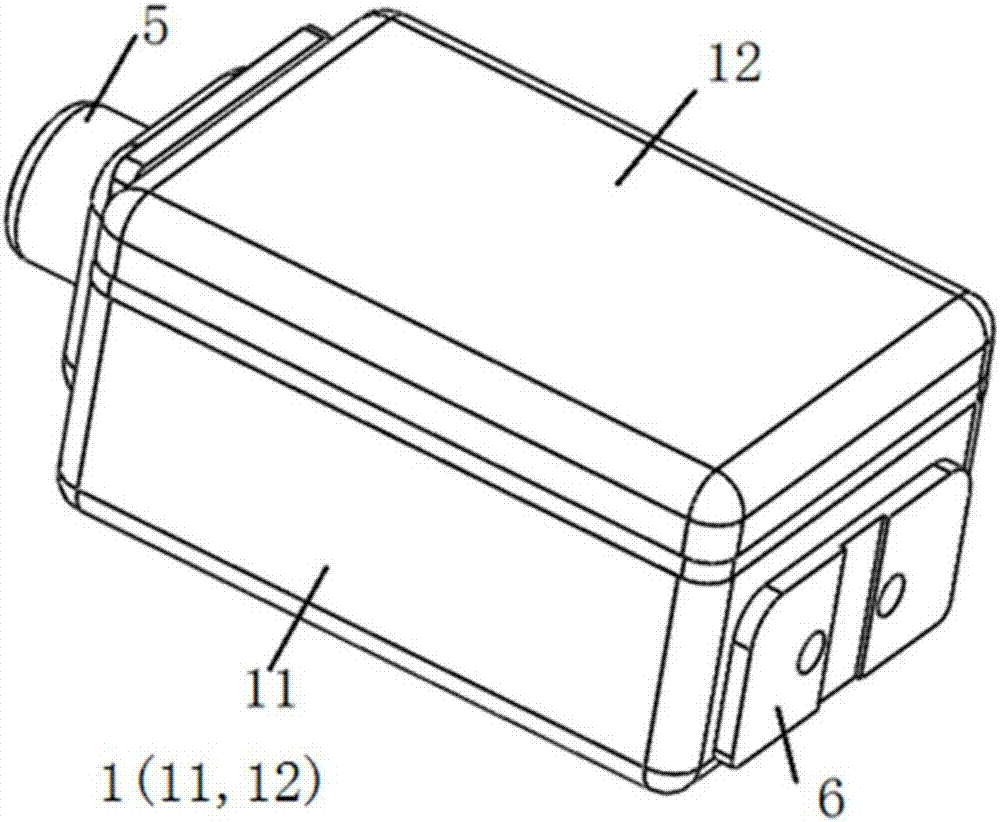
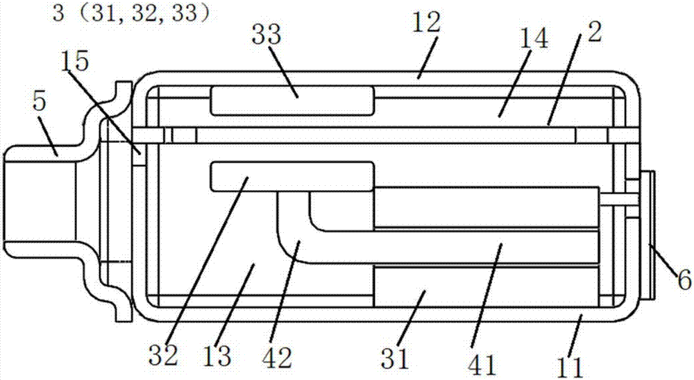
[0071] This embodiment provides a receiver, such as Figure 1 to Figure 3 As shown, it includes a casing 1 , a diaphragm mechanism 2 , an electromagnetic drive mechanism 3 , a welding pad 6 and a sound outlet tube 5 .

[0072] Such as figure 2 As shown, the shell 1 has a first shell 11 made of a first bottom surface and a side wall, and a second shell 12 made of a second bottom surface and a side wall; the second shell 12 is detachably connected to the first shell 11 buckle and encircle the inner cavity. The diaphragm mechanism 2 is arranged on the mouth edge (the edge of the opening) of the first housing 11 and the second housing 12, and divides the inner cavity of the housing 1 into an installation cavity 13 close to the first bottom surface and a second housing close to the bottom surface. Sound cavity 14 on the bottom surface. Correspondingly, the inner cavity of the first housing 11 forms the installation cavity 13 , and the inner cavity of the second housing 12 forms...

Embodiment 2

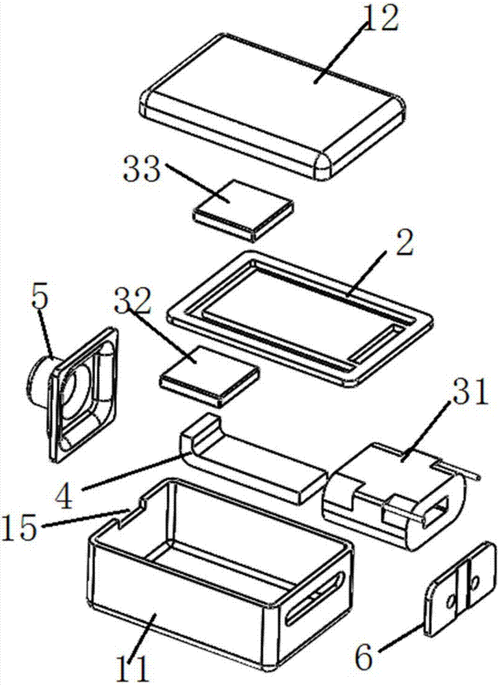
[0104] This embodiment provides an assembly process of a receiver, which includes a first shell 1, a second shell 1, a first coil, a second coil, a diaphragm mechanism 2, two conversion parts 4, a first magnet 32 ​​and a second magnet 33 . The specific steps of the assembly process are:

[0105] S1: Install the straight part 41 of the conversion element 4 in the first coil in advance, and then arrange the first coil on the inner wall surface of the first housing 11 parallel to the diaphragm mechanism 2, for example, the first coil of the first housing 11 A bottom surface, and then the first magnet 32 ​​is fixed on the bending part 42 of the conversion part 4 to form the first module;

[0106] S2: Pre-install the straight part 41 of another conversion element 4 in the second coil, and then arrange the second coil parallel to the diaphragm mechanism 2 on the inner wall surface of the second housing 12, such as the second housing 12 On the second bottom surface of the second ma...


PUM

PropertyMeasurementUnit
Caliberaaaaaaaaaa

Abstract

The invention discloses a receiver and an assembling process thereof. The receiver comprises a shell, a diaphragm mechanism and an electromagnetic drive mechanism. The diaphragm mechanism is arranged in the casing, which has a fixed frame, a reed and a sound film, and the sound film is pre-fixed on the fixed frame; the electromagnetic drive mechanism includes coils arranged parallel to the diaphragm mechanism, which are installed on the coils one by one and connect the coils to each other. The electromagnetic wire that generates the magnetic field is transformed from the direction parallel to the diaphragm mechanism to the transformation member in the vertical direction. The assembly process is as follows: the first coil with the conversion piece is installed on the first casing, the first magnet is fixed on the conversion piece; the second magnet is fixed on the inner wall surface of the second casing, and the two magnets are opposite and face each other. The polarity of one end is reversed; install the diaphragm mechanism on the inner wall of the housing. The diaphragm mechanism is used as a single module as a whole. When installing the receiver, the diaphragm mechanism only needs to be fixed on the shell through the fixing frame, which simplifies the installation process of the receiver. The conversion piece reduces the height occupied by the coil within the receiver.

Description

technical field [0001] The invention relates to the technical field of receivers, in particular to a receiver and an assembly process thereof. Background technique [0002] The receiver is an electroacoustic device that converts audio electrical signals into audio signals without sound leakage. It is widely used in communication terminal equipment such as mobile phones, fixed phones, and earphones to realize audio output. [0003] With the continuous development of mobile devices, the structure of the receiver is constantly updated. For example, the receiver disclosed in Chinese patent document CN103067806A integrates the reed and flapping mechanism in the traditional moving iron receiver to form a new diaphragm mechanism. Including the shell, the diaphragm mechanism installed horizontally in the inner cavity of the shell; the diaphragm mechanism includes an E-shaped reed, a coil set on the root of the E-shaped middle wall, and the other end of the reed is used as the vibrat...

Claims


Application Information

Patent Timeline
IPC IPC(8): H04R1/10
CPCH04R1/1058H04R2201/105
Inventor 吴哲
Owner SUZHOU YICHUAN TECH CO LTD
Why Eureka
Try Eureka