
Directional valve with check valve function

A directional valve and check valve technology, applied in the direction of functional valve type, valve operation/release device, lift valve, etc., can solve the problems of difficult closing of the plunger, high beam speed, etc., and achieve the effect of complete opening and convenience.

Active Publication Date: 2020-11-10
ROBERT BOSCH GMBH
View PDF4 Cites 0 Cited by
  • Summary
  • Abstract
  • Description
  • Claims
  • Application Information

AI Technical Summary

Problems solved by technology

However, it has been shown that this makes it difficult for the plunger to close reliably
The reason for this is that, with a small opening of the plunger, high jet velocities occur in the region of the plunger edge in the region of the first end face and only small pressures can be measured (abgreifen).

Method used


Image

  • Directional valve with check valve function
  • Directional valve with check valve function
  • Directional valve with check valve function

Examples


Embodiment Construction

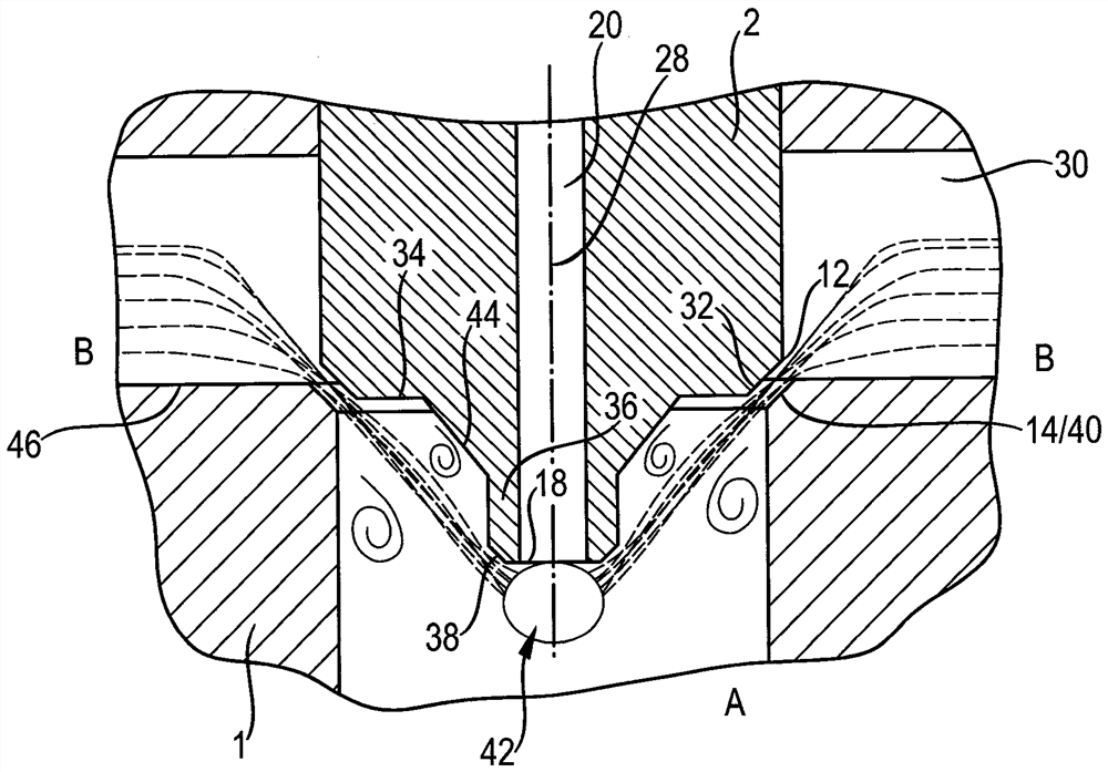
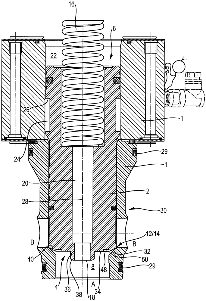
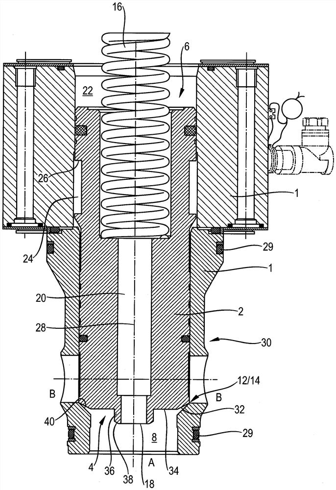
[0032] figure 1A first exemplary embodiment of a directional valve according to the invention is shown, which is designed as an active logic valve. It has a two-component valve housing 1 in which a stepped plunger 2 is guided. The plunger 2 has a first end side 4 and a second end side 6 opposite the first end side. In the region of the first end side 4 there is an outlet-side pressure chamber 8 which communicates with the outlet port A, while an inlet port B formed by radial bores is arranged on the outer circumference of the plunger 2 .

[0033] In active logic valve's or plunger 2's figure 1 In the closed position shown in , the edge 12 of the first end side 4 of the plunger 2 presses into the housing-side valve seat 14 . To this end, the force of a spring 16 acts, which is partially inserted into the second end side 6 of the plunger 2 and which bears against a section (not shown) of the valve housing 1 . Furthermore, the pressure of the outlet connection A acts in the c...


PUM


Abstract

A directional valve with non-return valve function is provided with a plunger, which has a first end surface that works in an opening direction and is loaded by pressure of a first joint; the plunger is provided with a second end surface, which works in a closing direction and is loaded by pressure of the first joint; to connect the two end surfaces, a tapping portion is arranged on the first end surface and is connected to the second end surface; a varying distance is formed between a voltage stagnation point and the tapping portion so that the pressure on the tapping portion fits different opening positions of the plunger.

Description

technical field [0001] The invention relates to a directional valve with the function of a non-return valve, the directional valve having a plunger via which a pressure medium connection between an inlet connection and an outlet connection can be controlled, wherein a first end of the plunger side is applied with pressure on the output joint, and the directional valve has a central tap for the control pressure agent, through which the control defined by the second end side of the plunger The pressure chamber is subjected to a pressure on the outlet connection. Background technique [0002] A directional valve of this type has a plunger, on the circumference of which an inlet connection is arranged, and on a first end side of the plunger an outlet connection is arranged. The first end side of the plunger is subjected to the pressure of the outlet connection. The pressure is also transmitted (in addition) via one or more plunger bores serving as compensating channels to the ...

Claims


Application Information

Patent Timeline
Patent Type & Authority Patents(China)
IPC IPC(8): F16K15/06F16K1/36F16K1/42F16K27/02
CPCF16K1/36F16K1/42F16K15/063F16K27/0209F16K1/38F16K31/1223F16K31/124F16K39/022
Inventor G.绍佩尔W.策
Owner ROBERT BOSCH GMBH
Learn More