
Electro-mechanical dual control pilot valve for unloading valve

An electromagnetic pilot valve and pilot valve technology are applied in the direction of mechanical equipment, fluid pressure actuators, servo motor components, etc., which can solve the problems of increased manufacturing cost, difficult manufacturing, inconvenient maintenance, etc., to reduce the overall size, reduce Effects that are difficult to manufacture and simple in structure

Active Publication Date: 2014-09-24
BEIJING TIANMA INTELLIGENT CONTROL TECH CO LTD +1
View PDF9 Cites 0 Cited by
  • Summary
  • Abstract
  • Description
  • Claims
  • Application Information

AI Technical Summary

Problems solved by technology

However, the technical problem in the above technical solution is that installing an electronically controlled bypass switch valve in the pilot valve body is difficult to manufacture and inconvenient to maintain, and it needs to be connected with the electromagnetic pilot valve through a transition connecting plate, and the overall structure is relatively complicated. ; while the electronically controlled bypass switch valve is installed outside the pilot valve body, since the electromagnetic pilot valve is located below the electronically controlled bypass switch valve, it not only occupies a large space, but it is also inconvenient to maintain the electromagnetic pilot valve from the bottom. In addition, in order to ensure the electronic control The high reliability of unloading and hydraulic control unloading requires an external one-way valve to store high-pressure fluid, so that before the pump is started next time, the solenoid valve of the pilot valve of the unloading valve can be controlled by high-pressure fluid to achieve no-load The purpose of starting
In order to ensure that the valve will not be polluted by the working fluid containing dirt, an external filter is also required. Since the check valve and filter are both external, the overall size of the equipment is relatively large, and some connectors are required, which increases the manufacturing cost.

Method used


Image

  • Electro-mechanical dual control pilot valve for unloading valve
  • Electro-mechanical dual control pilot valve for unloading valve
  • Electro-mechanical dual control pilot valve for unloading valve

Examples


specific Embodiment approach 1

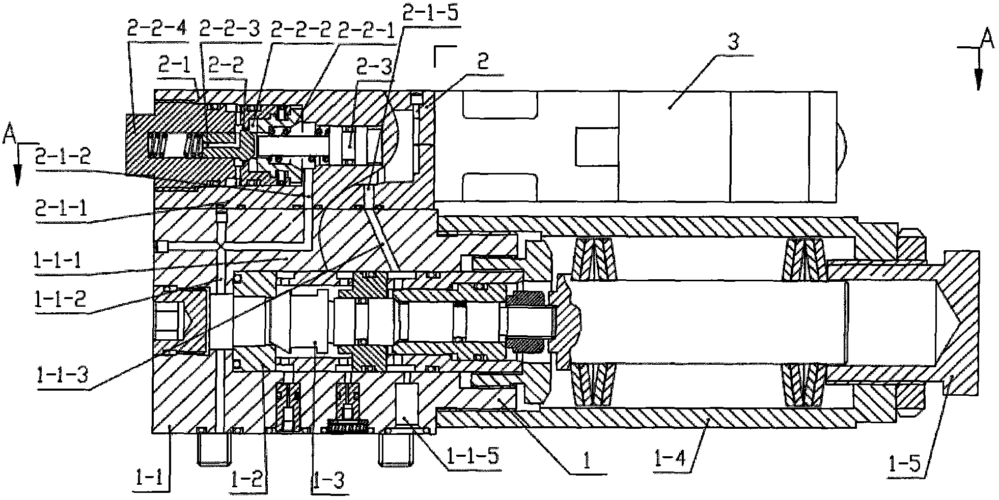
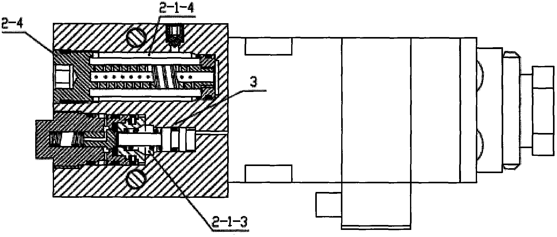
[0046] As shown in the accompanying drawings, the present invention includes a mechanical pilot valve 1, an auxiliary valve 2 that functions as an electronically controlled bypass switch valve, and an electromagnetic pilot valve 3. The auxiliary valve 2 is installed on the back of the mechanical pilot valve 1; The valve 3 is installed on the auxiliary valve 2. The mechanical pilot valve 1 includes a valve body 1-1, a valve seat 1-2, a valve core 1-3, a spring sleeve 1-4 and a pressure regulating screw 1-5. The valve body 1-1 is processed with a valve body first liquid channel 1-1-1 communicating with a process hole, a valve body second liquid channel 1-1-2 communicating with a process hole, and an incoming liquid port 1-1. -5 communicated valve body communication hole 1-1-3; the auxiliary valve 2 includes an auxiliary valve body 2-1, a cartridge valve core 2-2 and an auxiliary valve ejector rod 2-3, and the auxiliary valve body 2-1 The first liquid passage 2-1-1 and the auxili...

specific Embodiment approach 2

[0047] On the basis of Embodiment 1, the filter element 2-4 installed in the second main hole 2-1-4 of the auxiliary valve body is replaced with the filter element 2-5 containing the accumulator quick connector seat 2-5-1.

specific Embodiment approach 3

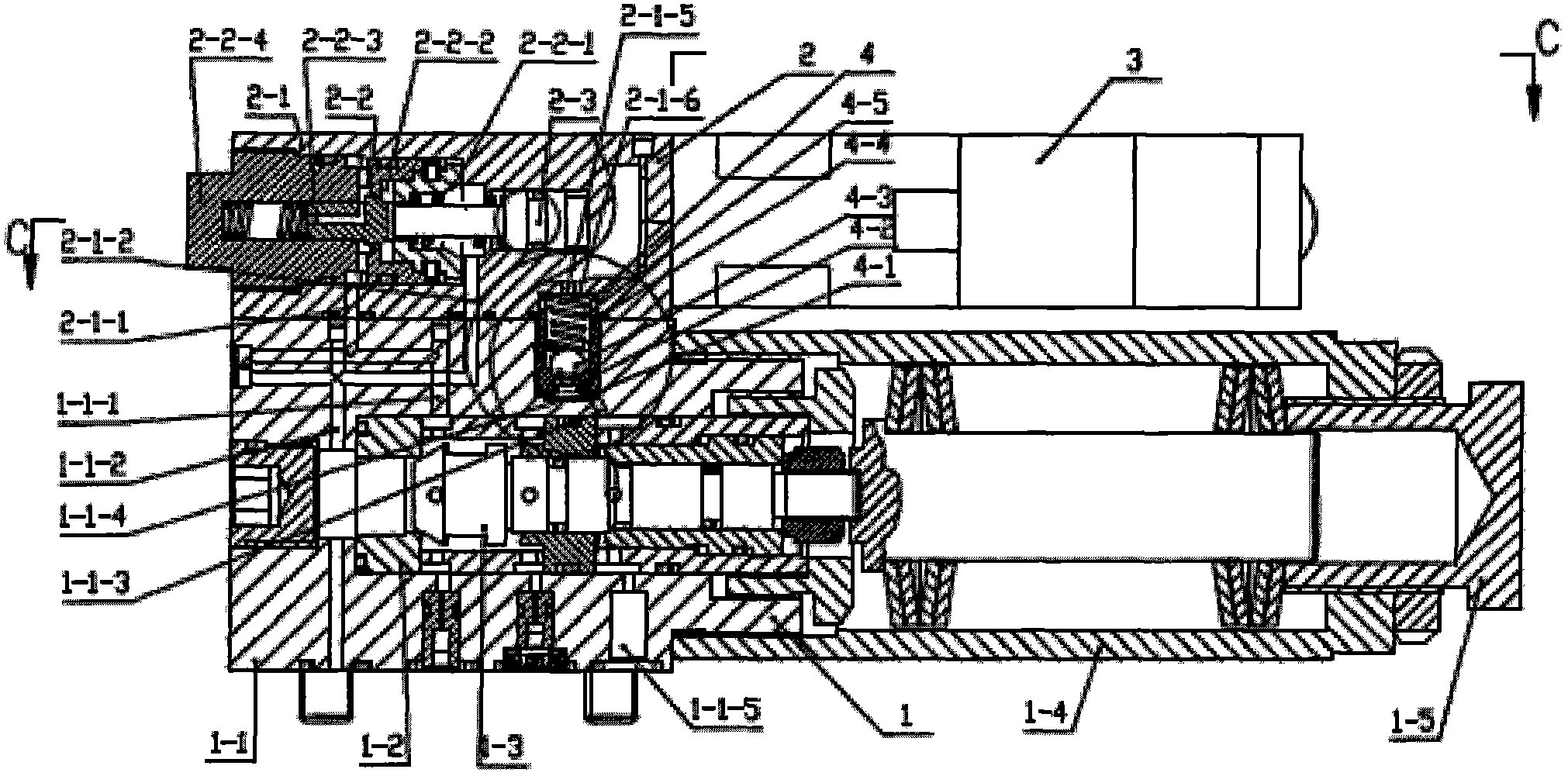
[0048]On the basis of specific embodiment 1 or specific embodiment 2, a valve body counterbore 1-1-4 communicating with the valve body communication hole 1-1-3 is processed on the valve body 1-1. The auxiliary valve body 2-1 is processed with an auxiliary valve body counterbore 2-1-6 communicated with the auxiliary valve body communication hole 2-1-5, and the auxiliary valve body sink hole 1-1-3 and the auxiliary valve body sink The holes 2-1-6 form the inner cavity of the one-way valve, and the one-way valve assembly 4 is installed in the inner cavity of the one-way valve, and the one-way valve assembly 4 includes a limit piece 4-1, a one-way valve seat 4-2 , steel ball 4-3, connection sleeve 4-4 and spring 4-5.

[0049] The high-pressure liquid enters the communication hole 1-1-3 of the valve body through the incoming liquid port 1-1-5, then enters the communication hole 2-1-5 of the auxiliary valve body, and then enters the second main hole 2-1-4 of the auxiliary valve body...


PUM


Abstract

The invention discloses an electro-mechanical dual control pilot valve for an unloading valve. The problems of complicated structure, large manufacture difficulty and maintaining inconvenience in the prior art are overcome. The electro-mechanical dual control pilot valve for the unloading valve is characterized in that a valve body communication hole and a secondary valve body communication hole are interconnected to form a high-pressure fluid channel for supplying liquid by a solenoid pilot valve, or a valve body counter bore is added to form the high-pressure fluid channel for supplying liquid by the solenoid pilot valve together with a secondary valve body counter bore and a one-way valve assembly; the valve body communication hole and the secondary valve body communication hole are correspondingly communicated to form a liquid inlet channel and a liquid return channel; two secondary valve body main holes are processed on the secondary valve body; a cartridge valve core is inserted into a first main hole of the secondary valve body; a filter core or the filter core containing a rapid joint seat externally connected with an accumulator is arranged inside a second main hole of the secondary valve body; and the secondary valve is arranged on the back side of a mechanical pilot valve, and the solenoid pilot valve is arranged on the secondary valve. The electro-mechanical dual control pilot valve has the beneficial effects that high-pressure liquid does not need to be externally connected; the filter and the one-way valve do not need to be externally connected, and the electro-mechanical dual control pilot valve has the filter function and one-way valve function, is simple in structure, reduces the manufacture difficulty and brings about convenience for maintenance.

Description

technical field [0001] The invention belongs to the technical field of pumping station control equipment, in particular to an electromechanical double-control pilot valve used for an unloading valve of a coal mine emulsion pump. Background technique [0002] The pilot valve of the hydraulic control unloading valve of the emulsion pumping station in the prior art is composed of a valve body, a valve seat, a valve core, a booster piston, a strong spring, a pressure introduction throttle plug, a pump inlet fluid throttle plug and a control piston section. The pilot valve of this hydraulic control structure can only realize hydraulic control unloading, and the pressure fluctuation value is relatively large. Human control is required. In the prior art, there is also a mechanism that installs hydraulically controlled unloading and electronically controlled unloading on a set of devices at the same time, but it can only realize electronically controlled unloading or hydraulically ...

Claims


Application Information

Patent Timeline
Patent Type & Authority Patents(China)
IPC IPC(8): F15B13/02
Inventor 李继周
Owner BEIJING TIANMA INTELLIGENT CONTROL TECH CO LTD
Learn More