
Hydraulic control lines for hydraulically controlled pouring units

A control circuit, hydraulic technology, applied in the direction of servo meter circuit, fluid pressure actuating device, servo motor, etc., can solve the problem of high cost of hydraulic control circuit, and achieve the effect of reducing cost

Active Publication Date: 2018-04-13
ROBERT BOSCH GMBH
View PDF8 Cites 0 Cited by
  • Summary
  • Abstract
  • Description
  • Claims
  • Application Information

AI Technical Summary

Problems solved by technology

[0005] This technical solution also has the disadvantage that the design of the hydraulic control circuit is extremely expensive in terms of equipment technology and / or regulation technology

Method used


Image

  • Hydraulic control lines for hydraulically controlled pouring units
  • Hydraulic control lines for hydraulically controlled pouring units
  • Hydraulic control lines for hydraulically controlled pouring units

Examples


Embodiment Construction

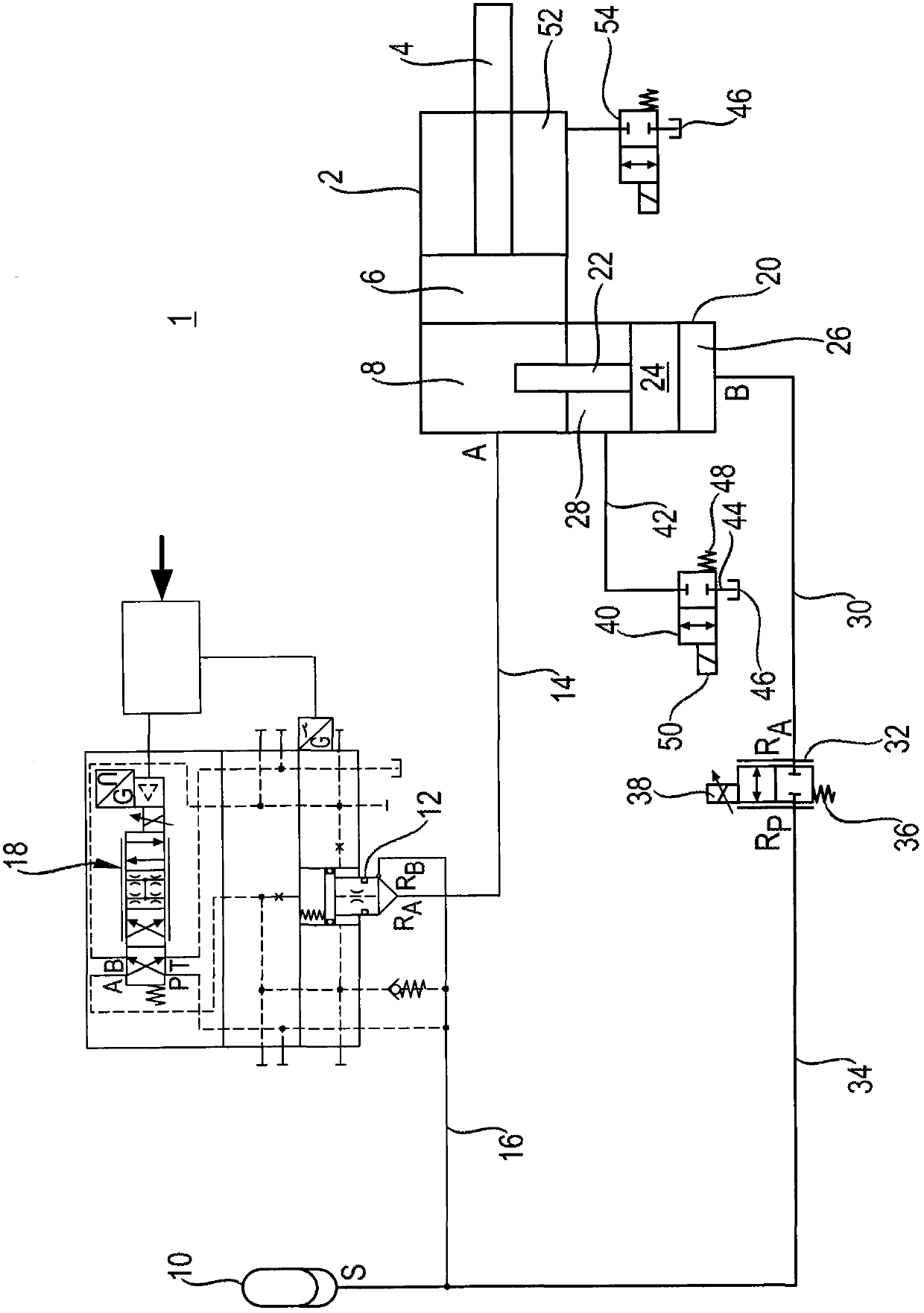
[0030] according to figure 1A hydraulic control line 1 is shown for a pouring cylinder 2 which is designed as a differential cylinder with a piston rod 4 on one side. The casting cylinder 2 is part of a hydraulic drive of a pressure casting machine, in particular a cold chamber pressure casting machine. It is also conceivable to use the hydraulic control line 1 with the pouring cylinder 2 for similar pouring or injection units, such as, for example, thixomolding or other die-casting machines. The pouring cylinder 2 can be used to inject molten or viscous molding material into the mold cavity of the tool. Due to the rapid solidification process, the injection process or emission takes place at high speed. High pressure is then applied to completely fill the tool cavity and to compact and to compensate for material shrinkage.

[0031] The mold filling process or pouring process can be subdivided into three stages. In a first stage, the molten molding compound is introduced i...


PUM


Abstract

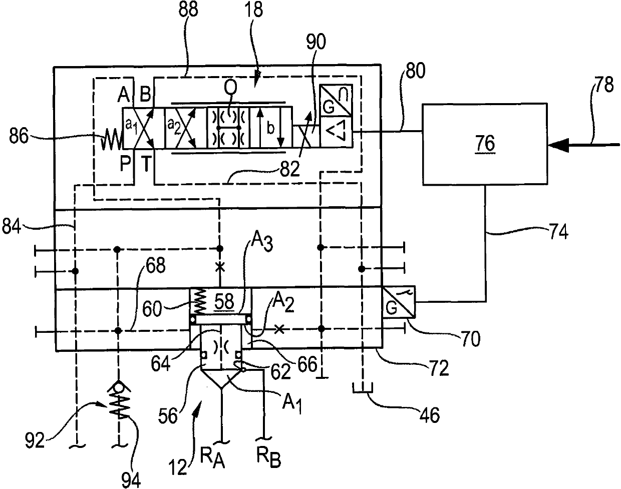
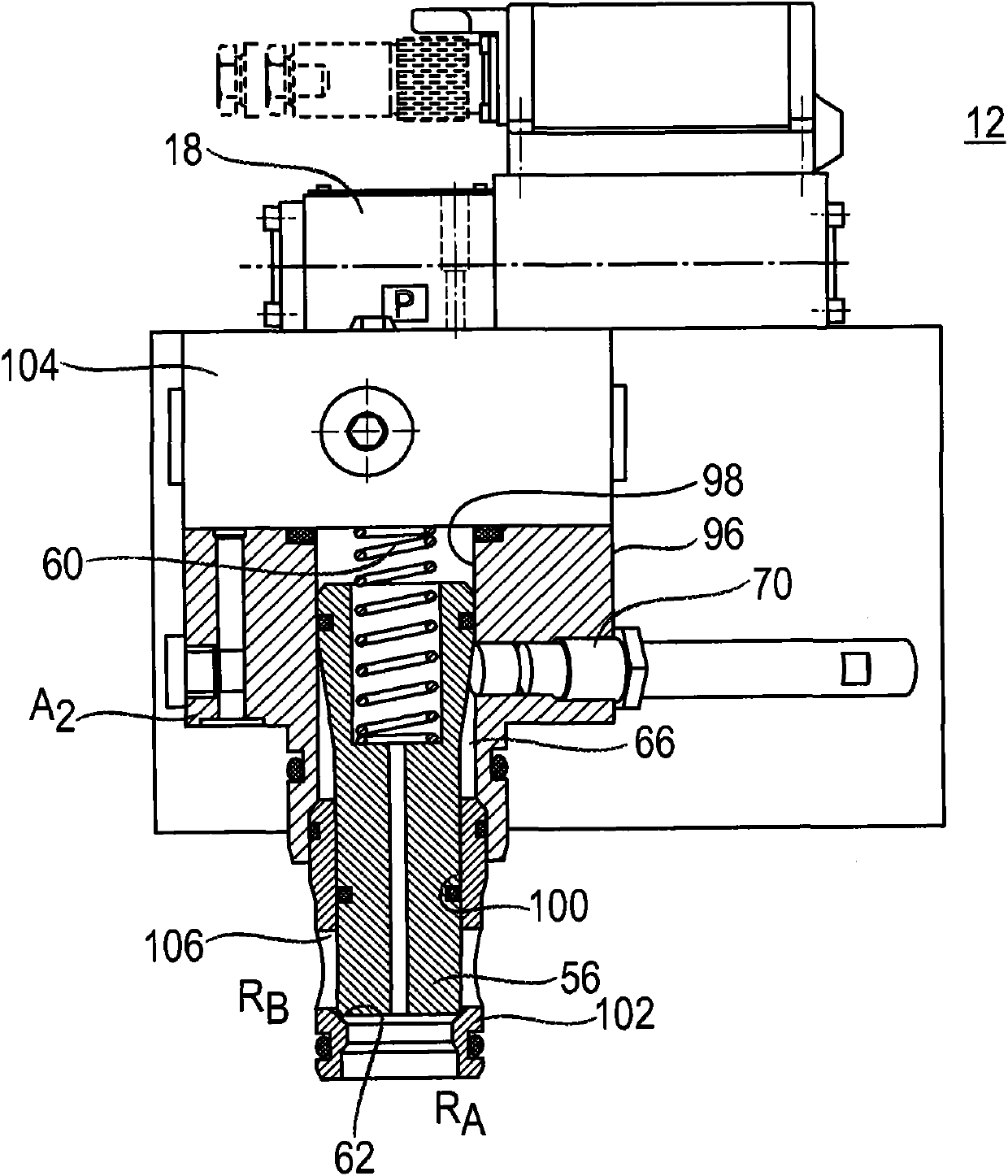
In particular, the invention discloses a hydraulic control circuit for a load, in particular for a pouring cylinder. The hydraulic control line has an active logic valve, which serves on the one hand as a check valve to prevent pressure medium from overflowing into the low-pressure branch and on the other hand as a proportional flow control valve. In order to use the active logic valve as a flow regulating valve, a pilot valve is provided, and the pilot valve is used to control the active logic valve.

Description

technical field [0001] The invention relates to a hydraulic control circuit for a load. Background technique [0002] Such a hydraulic control circuit is disclosed in DE 10 2005 035 170 A1. The hydraulic control circuit has a pouring cylinder configured as a differential cylinder with a piston rod on one side, the cylinder chamber of which is delimited by the piston can be connected to the low-pressure branch and is fluidly arranged parallel to the low-pressure branch. High voltage branch connection. The low-pressure branch is used for starting the casting cylinder and for the rapid progress of the infeed phase (Einzugphase) and the mold filling phase (Formfüllphase). Set up a high-voltage branch for the pressure-holding phase. The low-pressure branch connected to the low-pressure accumulator has a non-return valve in order to prevent pressure medium from escaping from the high-pressure branch into the low-pressure branch. The non-return valve is designed as a central va...

Claims


Application Information

Patent Timeline
Patent Type & Authority Patents(China)
IPC IPC(8): F15B11/08B22D17/32
CPCB22D17/32F15B11/0325F15B13/0405F15B13/0433F15B2013/0409F15B2211/216F15B2211/30515F15B2211/40515F15B2211/428F15B2211/455
Inventor H·恩格特
Owner ROBERT BOSCH GMBH
Learn More