Sub-surface defect shape reconstruction method for thermal imaging detection

A sub-surface defect and thermal imaging technology, applied in the direction of material defect testing, etc., to achieve the effect of quantitative analysis

Active Publication Date: 2017-08-01
UNIV OF ELECTRONICS SCI & TECH OF CHINA
View PDF10 Cites 17 Cited by
  • Summary
  • Abstract
  • Description
  • Claims
  • Application Information

AI Technical Summary

Problems solved by technology

[0004] The purpose of the present invention is to overcome the deficiencies of the prior art, and propose a method for reconstructing the shape of subsurface defects in thermal imaging detection, so as to facilitate the quantitative evaluation of subsurface defects and solve the problem of quantifying subsurface defects when surface excitation is used. analyse problem

Method used


Image

  • Sub-surface defect shape reconstruction method for thermal imaging detection
  • Sub-surface defect shape reconstruction method for thermal imaging detection
  • Sub-surface defect shape reconstruction method for thermal imaging detection

Examples


Embodiment Construction

[0027] Specific embodiments of the present invention will be described below in conjunction with the accompanying drawings, so that those skilled in the art can better understand the present invention. It should be noted that in the following description, when detailed descriptions of known functions and designs may dilute the main content of the present invention, these descriptions will be omitted here.

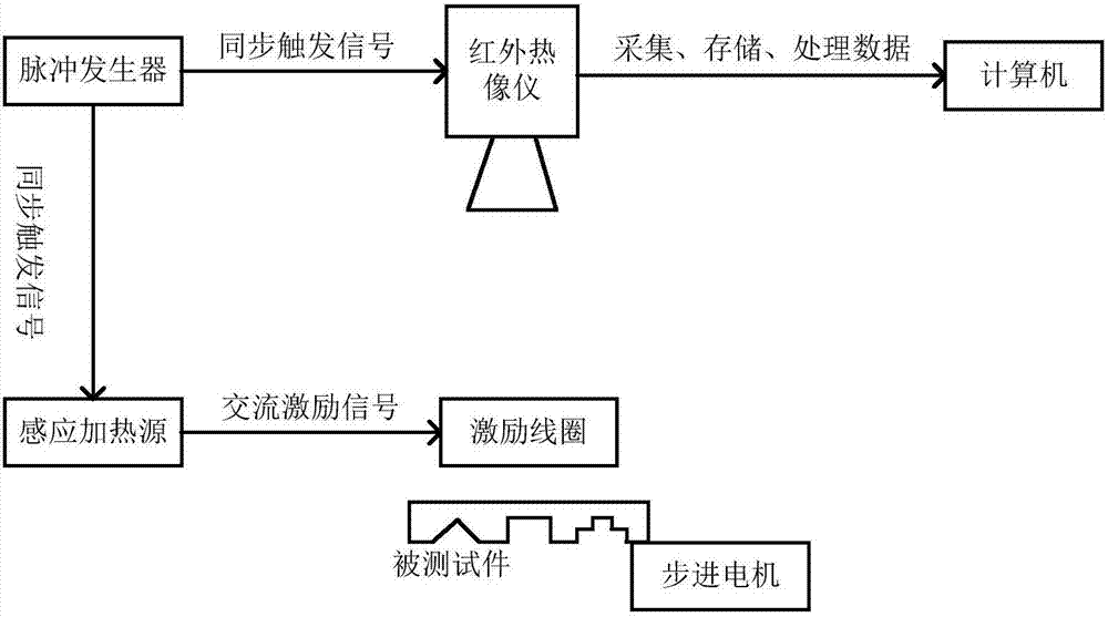
[0028] figure 1 It is a schematic diagram of the structure of the infrared thermal imaging non-destructive testing system.

[0029] In this example, if figure 1 As shown, the infrared thermal imaging non-destructive testing system usually consists of four parts: (1) thermal excitation part (induction heating source and excitation coil); (2) infrared thermal image acquisition part (infrared thermal imager); (3) control test Part moving part (stepping motor); (4) infrared thermal image processing and analysis part (computer); in addition, it also includes a pulse generator ...


PUM


Abstract

The invention discloses a sub-surface defect shape reconstruction method for thermal imaging detection. The sub-surface defect shape reconstruction method consists of a thermal response signal acquisition process, a process of solving a phase difference between a defective region and a non-defective region, and a process of reconstructing a defect shape by adopting an envelope line. The method comprises the following steps: performing linear scanning on a test piece by adopting a linear thermal source; then performing Fourier analysis on data at a collected heating source position; solving corresponding phase differences between other position and non-defective positions; reversing the depths of defects according to the phase differences; then, making an envelope line according to scanning results of position lines, namely, solved depths; finally, estimating the shapes of the defects according to the envelope line. By adopting the sub-surface defect shape reconstruction method, the shapes of irregular defects can be estimated and reconstructed, quantitative assessment can be performed on the defects, and the problem on the aspect of quantitative analysis of the defects of the type during surface excitation is solved.

Description

technical field [0001] The invention belongs to the technical field of non-destructive testing of specimens containing subsurface defects, and more specifically relates to a shape reconstruction method for subsurface defects in thermal imaging testing. Background technique [0002] With the continuous development of science and technology, the quality and safety of mechanical equipment or components has become an issue of increasing concern. Infrared thermal imaging non-destructive testing technology plays an indispensable role in the safe operation of equipment, product quality control and ensuring that equipment is in a safe and reliable state. With its unique advantages, infrared thermal imaging non-destructive testing technology has become a new type of digital testing technology that is currently focused on development. Compared with traditional detection technology, it has the advantages of wide application range, non-contact, fast speed, on-site use, high precision, ...

Claims


Application Information

Patent Timeline
Patent Type & Authority Applications(China)
IPC IPC(8): G01N25/72
CPCG01N25/72
Inventor 白利兵朱晨晨程玉华陈雪张杰殷春甘文东何棱云
Owner UNIV OF ELECTRONICS SCI & TECH OF CHINA
Why Eureka
Try Eureka