
Solenoid-powered conveying device

A push device, electromagnetic technology, applied in electromechanical devices, cleaning devices, transportation and packaging, etc., can solve problems such as push process and push speed mechanical interference

Active Publication Date: 2017-08-01
ROBERT BOSCH GMBH
View PDF11 Cites 0 Cited by
  • Summary
  • Abstract
  • Description
  • Claims
  • Application Information

AI Technical Summary

Problems solved by technology

Depending on the degree of contamination, there may also be mechanical disturbances in the push process and push speed

Method used


Image

  • Solenoid-powered conveying device
  • Solenoid-powered conveying device
  • Solenoid-powered conveying device

Examples


Embodiment Construction

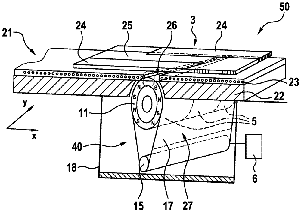
[0032] The invention is explained in detail with reference to the figures that follow. In this case, the same reference numerals designate the same components.

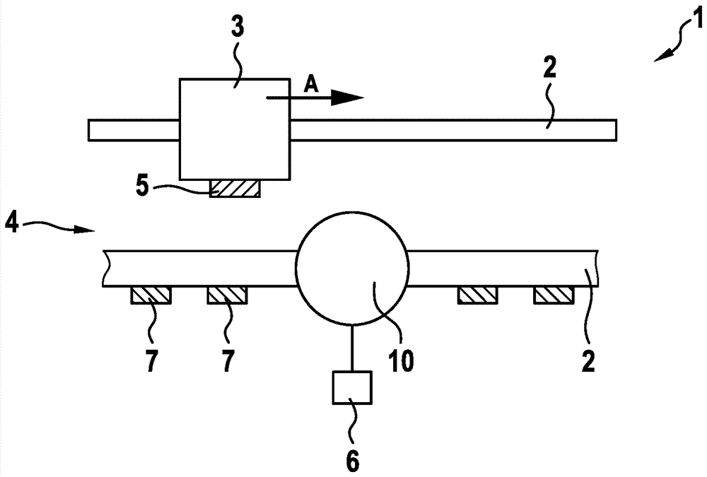
[0033] figure 1 A side view of a section of the pushing device 1 according to the first exemplary embodiment of the invention is schematically shown. The push device 1 comprises a linear drive 4 with a guide rail 2 and a push magnet 7 , wherein the push magnet 7 cooperates with a permanent magnet 5 arranged on the push element 3 (mover). The push device 1 according to the invention may comprise a plurality of push elements 3 .

[0034] exist figure 1 The push element 3 shown in FIG. 2 has a permanent magnet 5 on its bottom surface, but can also have a plurality of permanent magnets. During operation of the linear drive 4 , the permanent magnet 5 of the push element 3 and thus the push element 3 itself is moved in the direction of the arrow A by magnetic attraction or magnetic repulsion. For example, a load supporte...


PUM


Abstract

The present invention relates to a solenoid-powered conveying device comprising a movable conveying element (3), at least one permanent magnet (5, 24, 25) arranged on the conveying element (3) for moving the conveying element (3), and a cleaning device (10, 20, 30, 40) for removing particles from a surface of the permanent magnet (5, 24, 25).

Description

technical field [0001] The invention relates to an electromagnetically operated push device which, in order to ensure trouble-free operation, includes a cleaning device. The invention also relates to a method for cleaning the permanent magnets of such a push device. Background technique [0002] Magnet-operated or magnet-driven push devices are known from the prior art in a wide variety of designs. Thus, for example DE 1958177 A1 describes a push device with: a circumferential, endless, magnetizable push belt; and an endless drive chain acting on its inner side, provided with permanent magnets, so The driving chain is driven by a driving device. On the top side of the feed belt, the material can be pushed on suitable magnetic feed elements, ie likewise provided with permanent magnets. A problem with all magnetically operated push devices is contamination of the permanent magnets. This leads in particular to local changes in the magnetic field. Depending on the degree of...

Claims


Application Information

Patent Timeline
Patent Type & Authority Applications(China)
IPC IPC(8): B65G45/10B65G54/02
CPCB65G45/10B65G54/02H02K2201/03H02K41/02
Inventor A.帕韦莱茨J.弗兰根H.拉茨
Owner ROBERT BOSCH GMBH
Learn More