Current sensing element and power transmission system
A current detection and component technology, applied in electrical components, voltage/current isolation, circuits, etc., can solve the problems of increased component size and low height of the converter, and achieve the effect of strong magnetic field coupling and high sensitivity
- Summary
- Abstract
- Description
- Claims
- Application Information
AI Technical Summary
Problems solved by technology
Method used
Image
Examples
Embodiment approach 1
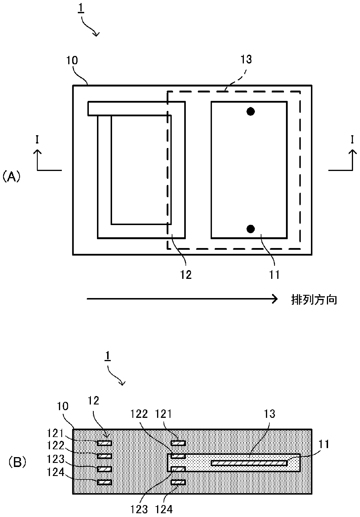
[0046] figure 1 (A) is a plan view of the current detection element 1, figure 1 (B) is figure 1 (A) Cross-sectional view at line I-I. in addition, figure 1 The top view shown in (A) is a perspective view.
[0047] The current detection element 1 includes a laminated body 10 , a main line electrode 11 , and a coil conductor 12 . The laminated body 10 is an insulator in which a plurality of insulator layers are stacked, and is formed by sintering. The insulator layer includes an insulator layer made only of a magnetic material such as ferrite and an insulator layer made of a magnetic material and a non-magnetic material. The magnetic body is a strong magnetic body, and the relative permeability μ r >1. The magnetic permeability of the non-magnetic body is lower than that of the surrounding magnetic body, and the relative magnetic permeability μ r=1. When these insulator layers are stacked, in the laminated body 10 , the high magnetic permeability portion is formed of a ...
Embodiment approach 2
[0069] In the current detection element according to the second embodiment, the size of the low magnetic permeability portion is different from that of the first embodiment.
[0070] Figure 4 (A) is a top view of the current detection element 2, Figure 4(B) is Figure 4 (A) Cross-sectional view at line IV-IV. in addition, Figure 4 The top view shown in (A) is a perspective view.
[0071] The laminated body 10A of the current detection element 2 is formed by laminating and sintering an insulator layer composed only of a ferromagnetic material such as ferrite and an insulator layer composed only of a nonmagnetic material. By laminating an insulator layer composed only of a nonmagnetic material, the low magnetic permeability portion 14 of the nonmagnetic material layer is formed in the laminated body 10A. Further, insulator layers made of only ferromagnetic materials are stacked along the stacking direction so as to sandwich the low magnetic permeability portion 14 thereb...
Embodiment approach 3
[0076] The current detection element according to Embodiment 3 differs from Embodiment 1 in that it includes two coil conductors for detecting current.
[0077] Figure 5 (A) is a plan view of the current detection element 3, Figure 5 (B) is Figure 5 (A) Cross-sectional view at line V-V.
[0078] The current detection element 3 is provided with the laminated body 20, the electrode 21 for main lines, and coil conductor 22A, 22B. The laminated body 10 is formed by laminating and firing a plurality of insulator layers. The insulator layer includes an insulator layer made only of a ferromagnetic material such as ferrite and an insulator layer made of a ferromagnetic material and a nonmagnetic material. When these insulator layers are stacked, the low magnetic permeability portion 24 whose magnetic permeability is lower than that of the surrounding area is formed in the laminated body 20 by a non-magnetic material.
[0079] The main line electrode 21 is formed in the low mag...
PUM
 Abstract
Description
Claims
Application Information
 - R&D
- Intellectual Property
- Life Sciences
- Materials
- Tech Scout
- Unparalleled Data Quality
- Higher Quality Content
- 60% Fewer Hallucinations
Browse by: Latest US Patents, China's latest patents, Technical Efficacy Thesaurus, Application Domain, Technology Topic, Popular Technical Reports.
© 2025 PatSnap. All rights reserved.Legal|Privacy policy|Modern Slavery Act Transparency Statement|Sitemap|About US| Contact US: help@patsnap.com


